Model LT-1900
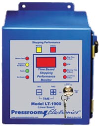
The model LT-1900 is a highly reliable, time-based stopping performance monitor designed for precision measurement and safety in machine operations. Utilizing a high-resolution linear transducer, it accurately measures the stopping time of a machine in milliseconds and the strokes per minute (SPM) of the press. The transducer attaches to the machine with a 1:1 linear ratio, ensuring consistent and precise data collection. Every machine stop is displayed in real-time on the bright red LED display on the unit’s front panel, making it easy to monitor stopping times and SPM during each machine cycle.
LT-1900 Applications/Categories: Time Based Stopping Performance Monitor
Package Includes: LT-1900 Controller, Linear Transducer, Mounting Brackets, Magnet, 40′ Transducer Cable, Installation and Operation Manual
Features
- Warning Indicator: A yellow light illuminates if the stopping time exceeds the setpoint, alerting operators and maintenance teams.
- Motion Failure Detection: A red LED signals when motion detection pulses are lost, providing immediate feedback.
- Stopped/No Motion Indicator: A yellow LED activates when valve power is off.
- Ready/Not Ready Indicators:
- Green LED: System ready and operational.
- Red LED: Safety relays deactivated due to faults or improper settings.
- Pushbutton Programming:
- Set stopping performance warning and limit time values in milliseconds with +/- pushbuttons for precision adjustments.
- Failure Alerts:
- A red LED warns when stopping time exceeds the programmed limit setpoint, ensuring compliance and proactive maintenance.
- Real-Time Display:
- Stopping Time: Visible in milliseconds after each stop.
- SPM: Displayed during each machine cycle.
- Stopping Performance Warning Time: Displayed in milliseconds
- Stopping Performance Limit Time: Displayed in milliseconds
Design Specifically for the Rigorous Metal Stamping and Forming Industry
- Compact, front-panel-mounted controller for easy installation and programming.
- Compatible with OEM systems, retrofits, and rebuilds.
- Durable, flat-panel design with NEMA 12-rated steel enclosure.
- Interfaces seamlessly with solid-state or relay-logic press controls.
- Solid state indicators – no incandescent bulbs that burn out
- Made in the USA.
Programming and Safety
- Setpoint Adjustment: Use the secure keyed selector switch and +/- buttons to set warning and failure thresholds (1–999 ms). Changes are locked while the machine is in motion for added safety.
- Non-Volatile Memory: EEPROM storage ensures settings and fault data are retained without battery backup, even during power loss.
- Dual Safety Relays: Force-guided relays automatically deactivate in fault conditions, preventing further operation until reset.
- Safety relays are always de-energized when the programming key is not in the Run position.
- Safety relays are energized when the programming key is in the Run position, as long as there are no faults detected.
- Only a key turn to the reset position can clear a fault, and the relays de-energize if the key is moved into the reset position without a fault.
- Motion Detection: Motion detection will be monitored while in the reset position, even if the linear transducer has motion.
Predictive Maintenance
The LT-1900 enables proactive maintenance by monitoring factors affecting stopping time, such as:
- Machine speed and tooling weight
- Wear adjustment and pressure
- Air supply
- Exhaust restrictions
Advanced Diagnostics
- Self-diagnostics display error codes for easy troubleshooting.
- Faults are stored in memory with the last recorded stopping time, simplifying maintenance and reducing downtime.
Compliance
The LT-1900 system complies with OSHA code 29 CFR 1910.217 and ANSI Codes B11.3-2012 (R2020) and
B11.2-2013 (R2020) for monitoring and control reliability standards. The unit will automatically prevent the activation of a successive stroke if the stopping time deteriorates beyond the brake limit setpoint.
Technical Specifications
Ordering Procedure
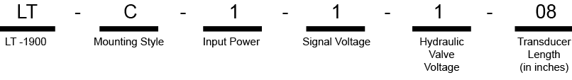
- Specify Mounting Style
- F: Front Panel Mounting to be installed in an existing control panel
- C: Stand-alone NEMA 12 (IP 64) steel enclosure.
- Specify Controller Input Power
- 1: 24 VDC
- 2: 120 VAC, 50-60 Hz
- Specify Hydraulic Valve Coil Voltage
- 1: 24 VDC
- 2: 120 VAC 50-60 Hz
- Specify Linear Transducer Length (Must Equal or Exceed Maximum Machine Stroke Length)
- 04: 4” (101 mm) active length
- 08: 8” (203 mm) active length
- 12: 12” (305 mm) active length
- 16: 16” (406 mm) active length
- 24: 24” (609 mm) active length
- *Consult Sales if over 24” (609 mm) is required.
Mounting Brackets: Supplied standard with each linear transducer
Cable Length: 40′ (12m) supplied standard with each linear transducer