PressCam 8
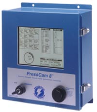
The PressCam 8 is a cutting-edge solution that combines a “control reliable” resolver-based programmable cam switch (PLS), time-based brake monitor, die protection system, multiple counters, and more into one comprehensive package. The system ensures robust reliability and precision with dual 16-bit computers configured to cross-check each other and the resolver.
An 8-inch (203 mm) diagonal LCD screen provides a clear, full-view interface for seamless programming and operation. This large display simplifies access, offering operators and front-line supervisors essential production data without cumbersome menus or program access codes. With a 100-job memory capacity, the PressCam 8 is built to optimize efficiency and performance.
PressCam 8 Applications/Categories: Punch Press Automation Controllers, Time Based Brake Monitoring, Programmable Limit Switches (PLS), Die Protection Systems, Servo Feed Interface, Tonnage Monitoring
Enhanced Troubleshooting and Simplified Programming
The PressCam 8 ensures quick troubleshooting with plain-English error messages displayed directly on the screen, allowing floor personnel to rapidly identify and address machine stoppages. Built-in watchdog features automatically disable fault outputs if either computer exhibits erratic behavior, ensuring safe and reliable operation.
Programming the PressCam 8 is remarkably intuitive, thanks to its innovative digital programming knob. Functioning like a computer mouse, the knob lets users simply turn to highlight a desired field or program, then push to access it—eliminating the need for keypads or keyboards. Numbers or letters for specific functions appear on the highlighted screen as you turn the knob; another push completes the programming. This streamlined process minimizes errors, as non-applicable functions are automatically restricted from being programmed.
Field upgrades for software and system customization are simple, requiring only a standard PC with a serial port. The large 8-inch LCD screen further enhances usability, providing operators and front-line supervisors with clear and immediate access to essential production data without cumbersome menus or program codes.
Features
Safety and Reliability
- “Control Reliable” dual 16-bit computers for enhanced safety.
- Fault outputs monitored by three captive contact safety relays for Form B safety.
- Built-in motion, brake, and drift detection with fault outputs.
- Programmable minimum and maximum speed limits with safety relay output.
- Punch press clutch/brake timing signals protected from tampering.
Ease of Use
- Large 8” (203 mm) LCD screen with contrast adjustment.
- Operator “full view” of system status
- Plain English fault messages for quick troubleshooting.
- Unique digital programming knob eliminates the need for a keypad.
Advanced Programmability
- Non-volatile memory stores up to 100 programs by job die number.
- Eleven programmable limit switch outputs with multiple ON/OFFs per cycle.
- Four programmable timed limit switch outputs (position or time-based from 0 to 9999 milliseconds).
- Four counters: Strokes, Parts, Batch, and Quality.
- Parts counter programmable from 1-4 parts per press cycle for multiple out dies.
- Programmable variable speed compensation.
- Automatic offset programming and built-in servo feed interface.
Diagnostics and Monitoring
- Complete system diagnostics displayed in plain English.
- Built-in time-based brake monitor with stop warnings.
- Crankshaft angle is displayed in degrees with a graphical clock.
- Built-in press tachometer (SPM).
- Built-in 90° and 270° stop time tester.
- Optional peak tonnage monitoring (up to 4 channels).
- Supervisor controlled RUN/PROG key switch with password protection.
Connectivity and Flexibility
- PressCam 8 can be used to supply the timing signals for clutch/brake press control.
- Cloning feature links multiple units via RS-232 for job copying.
- Field-upgradable software via PC with a standard serial port.
- Socketed job memory chips for easy transfer between units.
- Outputs can be solid state (AC or DC) or mechanical relays.
Design and Construction
- Compact size with surface mount technology.
- Optically isolated AC and/or DC inputs for sourcing or sinking.
- Built-in power supply for input sensors (+12 VDC).
Industrial Grade Brushless Resolver Transducer

The heavy-duty brushless resolver transducer replaces the current mechanical rotary cam switch. This unit was designed for hostile industrial environments such as punch press mechanical shock and vibration, extreme temperature and humidity, oil, coolant, and lubrication mists. The resolver transducer features excellent repeatability and gives absolute shaft position feedback. High-speed operation along with long transducer cable (runs up to 600 feet/183m) give the resolver wide application ranges. The resolver is a passive device that contains no sensitive electronics and has superb noise immunity.
The resolver mounts easily to the end of a crankshaft and can rotate clockwise or counter-clockwise. Simple connector-ended transducer cabling is supplied to connect the resolver to the PressCam 8 controller console. The PressCam’s microprocessor-based control constantly monitors the resolver position and displays both the angular position of the shaft and the speed of the machine (tachometer). 3/4” (19 mm) resolver shaft diameter.
Technical Specifications
Display Screens

The screen shown above represents the actual size and layout of the PressCam 8 Programming Screen, providing press operators with an intuitive and comprehensive interface. Gone are the days of navigating through endless menus and cumbersome programming techniques to access critical data. The Programming Screen features an active toolbar that allows press setup personnel to quickly access specific functions with ease. This single operator screen consolidates a wealth of production data, simplifying the operator experience.
Key information displayed includes:
- Four separate counters
- Fault reset functionality
- Adjustable screen contrast
- Die protection details
- Programmable limit switch data
- Shaft angle in degrees
- Strokes per minute (SPM)
- Brake monitoring metrics
When system faults occur, clear and concise messages are displayed in real-time within the designated area above the brake monitor setpoint section, ensuring quick identification and resolution of issues.
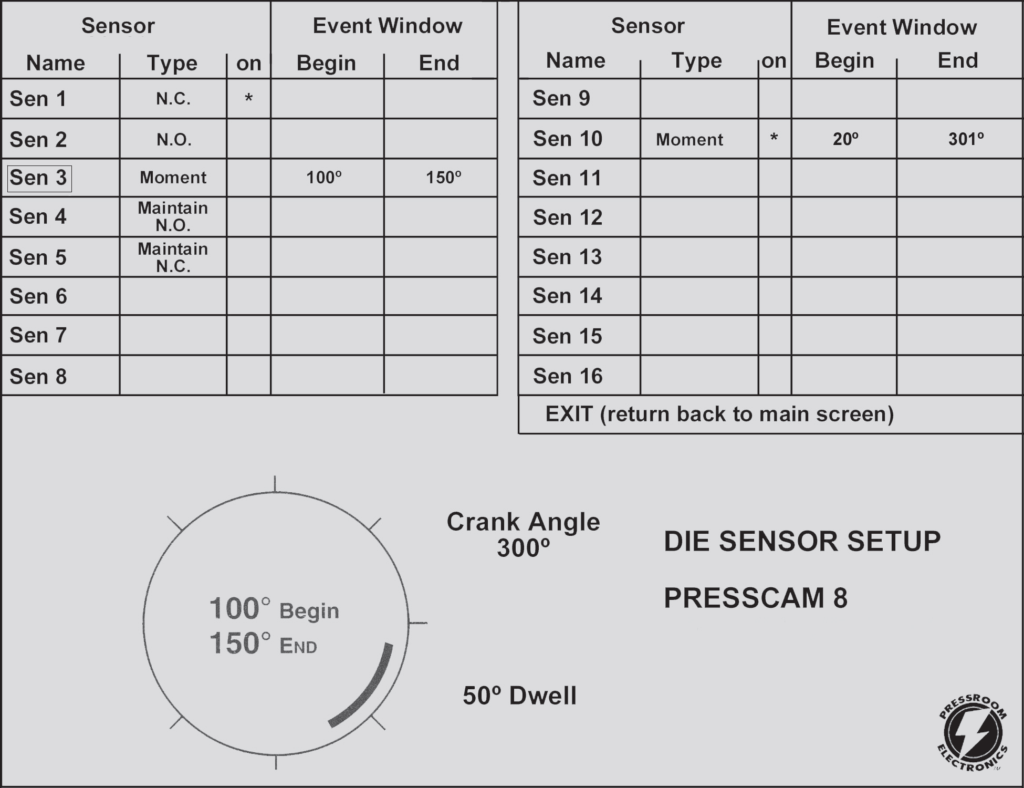
The Die Protection Screen shown above is the interface your programmer will use to access the die protection program. The PressCam 8 system supports 16 die protection sensor inputs, which can be programmed for cyclic and/or static function monitoring.
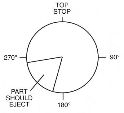
Cyclic function monitoring ensures that an input sensor signal occurs within a specific programmed shaft angle during each press cycle, such as for part ejection or transfer. Static monitoring, on the other hand, is designed for non-cyclic events like end-of-material or stock buckle monitoring.
For example, if a part must eject from the die between 190° and 250° of the machine cycle, the system will monitor for that transition. If the part is not detected within the specified parameters, the system generates a fault output or stop signal to halt the machine.
Simplified Programming Process:
- Navigate to the “Die-Sensor Set-Up” menu and select it using the programming knob.
- Input the desired parameters in degrees for monitoring (e.g., 190° to 250° for part ejection).
- The system will begin monitoring the programmed range for the specified action.
If a fault occurs, the screen will display clear information about the issue, including the specific sensor triggering the fault, allowing for quick diagnostics.
On-the-Fly Adjustments:
The die protection program can be fine-tuned while the machine is running. Peripheral signals, such as feeds, lubrication, and blow-offs, can also be adjusted simultaneously, enhancing machine efficiency and minimizing downtime.
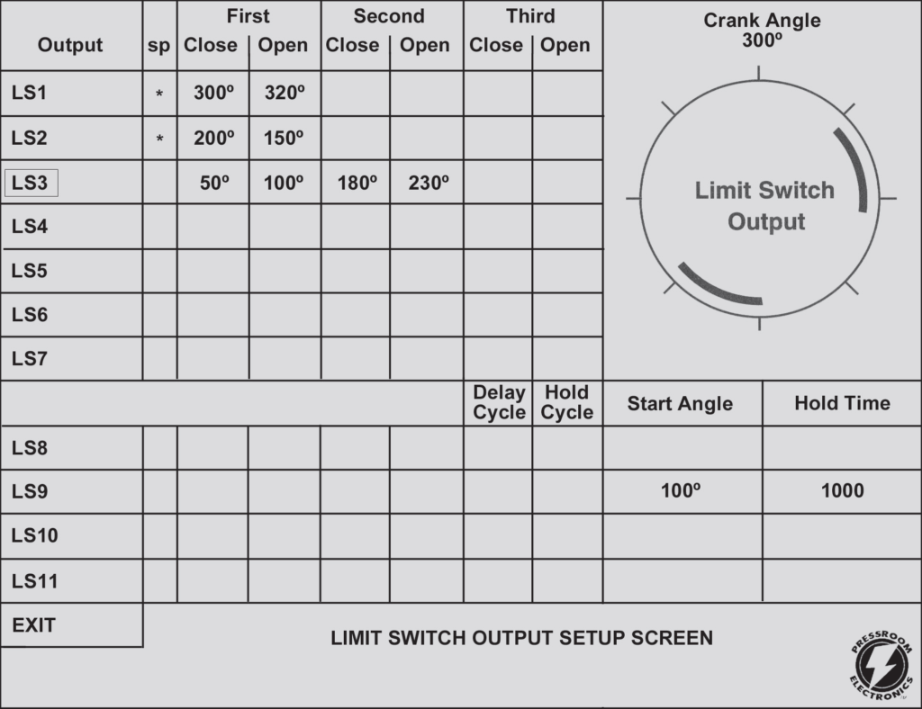
The PressCam 8 offers user-friendly limit switch programming powered by a heavy-duty industrial resolver driven by the press crankshaft. With 11 programmable limit switch outputs, the system can initiate various peripheral equipment with precision and reliability.
Key Features of Limit Switch Programming:
- Flexible Output Types: Outputs can be configured as mechanical relays or solid-state relays (AC or DC), with the option to mix relay types on the same board.
- Multiple ON/OFF Events:
- Limit switches 1–7 can be programmed for up to three ON/OFF cycles per press cycle.
- Limit switches 8–11 can be programmed for up to two ON/OFF cycles or configured to turn ON based on angle and OFF based on time.
- Precise Timing: Timed outputs can be programmed in increments ranging from 0.001 to 10 seconds.
Advanced Features for Greater Control:
- Delay and Hold Cycles:
- Control intermittent events, such as lubrication systems or scrap choppers.
- Program events to occur after a specific number of press cycles or maintain activation for a pre-set number of cycles.
- Speed Monitoring:
- Minimum and maximum speed limits can be programmed to monitor optimal running speeds.
- Deviations outside the programmed range trigger a stop signal, ensuring safe and efficient operation.
- True Motion Detection:
- If the press fails to move within the pre-programmed time (0.001 to 4 seconds) after initiation, a fault signal is generated.
- Conversely, if the press begins cycling without initiation, a fault signal disconnects all signals for safety.
Enhanced Security:
Clutch/brake timing signals are password-protected to prevent unauthorized tampering, safeguarding critical operations.

The TLM I/O Load Module is a high-performance device designed for critical force measurement applications requiring exceptional accuracy, stability, and reliable noise rejection. As a signal conditioning device without a display or alarms, the TLM serves as an input module for the PressCam 8, which provides display and alarm control functions. Its high sensitivity and dual amplifier gain ranges make it ideal for operating in electrically noisy environments and for accommodating both weak and strong signals from load sensors.
Key Features:
- Signal Conditioning: Compatible with strain gauge sensors and load cells.
- Multi-Channel Support: Four independent channels accommodate up to eight sensors.
- Sensor Compatibility: Supports full-bridge sensors ranging from 120 Ohms to 1,000 Ohms.
- Plug-and-Play Connections: Sensor inputs and power connectors use plug-in designs for easy setup.
- Dual Gain Ranges: High and low sensitivity span ranges, selectable via front-panel switches.
- Automatic Zero Balance: Ensures accurate measurements with minimal effort.
- Peak Load Memory: Built-in circuits for automatic peak load tracking with external trigger devices.
- Stable Operation: Integrated power supply for noise rejection and consistent performance.
- Compact Design: Small, durable steel enclosure provides maximum protection and fits almost any location.
Technical Specifications:
- Transducer Support
- Type: Full-bridge sensors (120–1,000 Ohms)
- Channels: 1 to 4, supporting up to 2 sensors per channel (maximum 350 Ohms per sensor)
- Dimensions
- 2″ (51 mm) x 3.1″ (79 mm) x 8.95″ (227 mm)
- Performance
- Balance Range: ±1 mV/V offset
- Gain:
- Low: Adjustable 100–1,100
- High: Adjustable 1,000–11,000
- Output Range: ±10 VDC at 12 VDC excitation
- Accuracy: Maximum ±1% of full scale
- Linearity: Maximum ±0.1% of full scale
- Auto Zero Time Constant: 10 seconds
- Frequency Response: Flat DC to 1 KHz
- Peak Decay: <1% of full scale over 10 minutes
- Calibration Shunts: 1 Meg Ohm, 0.1%
- Power Requirements
- Input Power:
- 100–130 VAC (50–60 Hz), fused at 0.10 Amp
- 200–260 VAC (50–60 Hz), fused at 0.05 Amp
- Input is jumper-selectable; fuses are 5 mm x 20 mm SLO-BLO
- Sensor Excitation: Internally supplied at +12 VDC, 0.30 Amps max.
- Input Power:
- Connections
- Sensor Input: Four-pin Phoenix connector with 0.2″ (5 mm) centers
- Peak Output: Six-pin Phoenix connector with 0.2″ (5 mm) centers
- Proximity Probe: 12 VDC internal supply for NPN or PNP probes (50 mA max) or dry relay contacts
This robust module offers superior force measurement capabilities, making it an indispensable component in demanding industrial environments.
Ordering Procedure
All styles (front panel and stand alone) include a resolver and cable.

- Specify Mounting Style
- F: Front Panel Mounting to be installed in an existing control panel.
- C: Stand alone NEMA12 enclosure
- T: Stand alone NEMA12 enclosure with room for the Tonnage Module
- Specify Output Relays (11 maximum)
- M: Mechanical Dry contact relays SPDT 10A@250VAC
- A: AC Solid State – single Pole N.O. 3A@140VAC, 12-140VAC, 25-70Hz
- D: DC Solid State – single Pole N.O. 3A@60VDC, 12-60VDC
- Specify Controller Input Power
- 1: 24 VDC
- 2: 120 VAC, 50-60 Hz
- 3: 240 VAC, 50-60 Hz
- Specify Clutch/Brake Valve Voltage
- 1: 24 VDC
- 2: 120 VAC, 50-60 Hz
- Resolver Connector Cabling
- 30’ (9m) of cable with connectors is supplied standard. If additional length is needed, specify in feet, 150’ (46m) maximum.
- Specify Tonnage Monitoring (optional)
- T1: One Channel monitoring with strain sensor and cable
- T2: Two Channel monitoring with strain sensor and cable
- T3: Three Channel monitoring with strain sensor and cable
- T4: Four Channel monitoring with strain sensor and cable
Additional Part: No. 30-012; 24vdc @ 2.2A power supply (90-260vac In) 3.9” L x 3.8” W x 1.4” H (99.1mm x 96.5mm x 35.6mm) for powering die protection sensors or other auxiliary devices.
For Custom Programming & Remote Field Upgrades, please consult factory at service@pressroomelectronics.com or (630) 443-9320.
Replacement Parts
Feature Comparison of PressCam 8 Junior and PressCam 8

For OSHA and ANSI Compliant Clutch/Brake Press Controls, please see the PressCommander.