PressCam 8 Junior
The PressCam 8 Junior is a resolver-based press automation controller designed to enhance precision and efficiency in press operations. It integrates a programmable cam limit switch, time-based brake monitor, servo feed control, four counters, and a die protection system, all powered by a 16-bit computer that continuously ensures resolver accuracy.
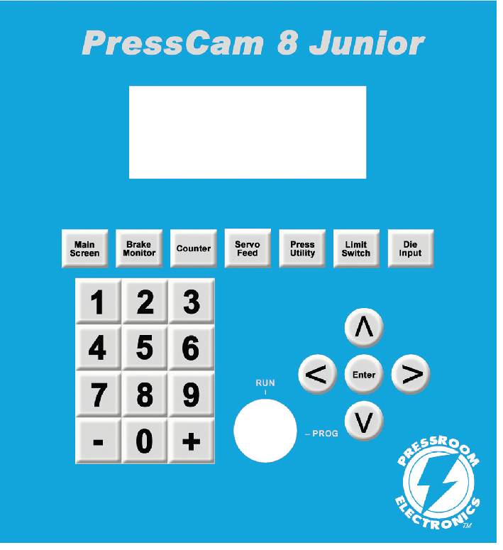
With a user-friendly interface, the PressCam 8 Junior features a keypad, menu, and cursor buttons for intuitive navigation, along with a four-line vacuum fluorescent display (20 characters per line) for clear and easy viewing. A “RUN/PROG” keyswitch adds operational security and flexibility. In “RUN” mode, users can clear counters and reset die sensor faults but cannot alter parameters or change jobs. In “PROG” mode, die faults are disabled to facilitate setups, while other faults remain active. For added security, the optional password feature requires users to enter a three-digit code to access the “PROG” mode and make parameter adjustments.
PressCam 8 Junior Applications/Categories: Punch Press Automation Controllers, Time Based Brake Monitoring, Programmable Limit Switches (PLS), Die Protection Systems, Servo Feed Interface
Features
Limit Switch Outputs
- Six small, high-speed, high-capacity relay outputs
- All six limit switch outputs can be programmed to cycle (non-timed) twice per crank rotation by setting open/close crank angles.
- The last three outputs support timed, non-timed, delayed, hold, or cycling twice per crank revolution.
Fault Management
- Handles critical faults such as E-stop, motion, brake, and sensor faults using two force-guided Form B safety relays.
- Brake and die sensor inputs are optically coupled and compatible with both AC and DC (sourcing or sinking) configurations.
Job Management
- Stores up to 100 jobs using a removable nonvolatile memory chip for easy job transfer.
- Each job can store a name or number with up to 7 characters for clear identification.
Monitoring and Detection
- Built-in brake monitor issues warnings if the programmed warning time is exceeded and signals failure if stop time is exceeded.
- True motion detection system identifies lack of motion (motion fault) and unintended motion (drift fault).
- Includes a strokes-per-minute (SPM) indicator.
- Displays crank angle graphically and with large numerical readouts.
Control and Security
- Speed compensation is available for user-selected outputs.
- Features a password and/or supervisory-controlled selector switch to prevent unauthorized parameter changes (counters can still be reset).
Interfaces and Connectivity
- Includes a servo feed interface.
- PCLink allows for offline job creation and storage.
Counters and Tracking
- Provides stroke, batch, quality, and part counters for operational tracking.
Diagnostics and Testing
- Built-in 90º and 270º stop time tester for enhanced diagnostics.
Industrial Grade Brushless Resolver Transducer

The heavy-duty brushless resolver transducer replaces the current mechanical rotary cam switch. This unit was designed for hostile industrial environments such as punch press mechanical shock and vibration, extreme temperature and humidity, oil, coolant, and lubrication mists. The resolver transducer features excellent repeatability and gives absolute shaft position feedback. High-speed operation along with long transducer cable (runs up to 600 feet/183m) give the resolver wide application ranges. The resolver is a passive device that contains no sensitive electronics and has superb noise immunity.
The resolver mounts easily to the end of a crankshaft and can rotate clockwise or counter-clockwise. Simple connector-ended transducer cabling is supplied to connect the resolver to the PressCam 8 controller console. The PressCam’s microprocessor-based control constantly monitors the resolver position and displays both the angular position of the shaft and the speed of the machine (tachometer). 3/4” (19 mm) resolver shaft diameter.
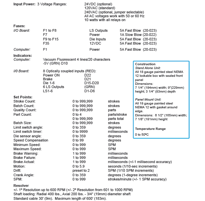
Technical Specifications
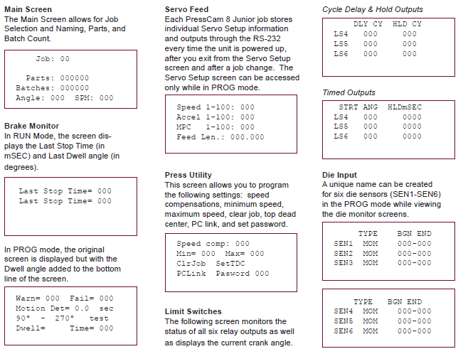
Display Screens
Ordering Procedure
All styles (front panel and stand alone) include a resolver and cable.
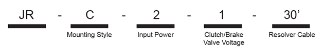
- Specify Mounting Style
- F: Front Panel Mounting to be installed in an existing control panel.
- C: Stand alone NEMA12 enclosure
- Specify Controller Input Power
- 1: 24 VDC
- 2: 120 VAC, 50-60 Hz
- 3: 240 VAC, 50-60 Hz
- Specify Clutch/Brake Valve Voltage
- 1: 24 VDC
- 2: 120 VAC, 50-60 Hz
- Resolver Connector Cabling
- 30’ (9m) of cable with connectors is supplied standard. If additional length is needed, specify in feet, 150’ (46m) maximum.
Additional Part: No. 30-012; 24vdc @ 2.2A power supply (90-260vac In) 3.9” L x 3.8” W x 1.4” H (99.1mm x 96.5mm x 35.6mm) for powering die protection sensors or other auxiliary devices.
For Custom Programming & Remote Field Upgrades, please consult factory at service@pressroomelectronics.com or (630) 443-9320.
Replacement Parts
Dimensions
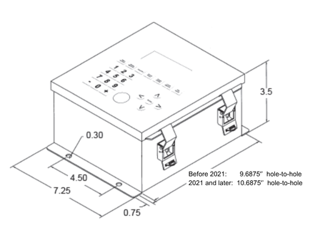
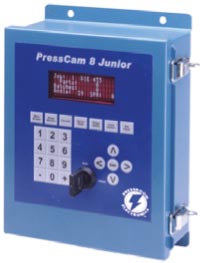
PressCam 8 Junior shown installed in a stand-alone NEMA 12 (IP64) lockable enclosure.
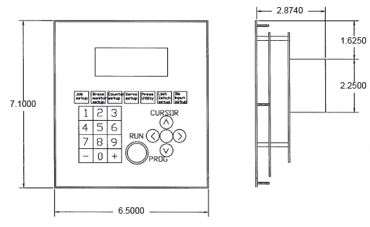
PressCam 8 Junior Front Panel Mount Cut-Out Dimensions
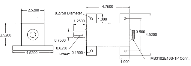
Resolver Transducer
Feature Comparison of PressCam 8 Junior and PressCam 8

For OSHA and ANSI Compliant Clutch/Brake Press Controls, please see the PressCommander.