PressCam 8
 PressCam 8
PressCam 8 is a “control reliable” resolver based programmable cam switch (PLS), time-based brake monitor, die protection system, multiple counters, and much more in one package. The system contains two 16-bit computers that are configured to cross check each other and the resolver. The dual computers are interfaced with a full view 8” (203mm) diagonal LCD computer screen for viewing and programming ease. This large operator screen supplies operators and front line supervisors production data without the need of cumbersome menu and program access codes. 100 job memory.
 PressCam 8 is a “control reliable” resolver-based programmable cam switch, time-based brake monitor, die protection system with multiple counters and much more in one package. The system contains two 16‑bit computers that are configured to cross check each other and the resolver. The dual computers are interfaced with a full view 8″ (203mm) diagonal LCD computer screen for viewing and programming ease. This large operator screen (shown on the next page) supplies operators and front line supervisors production data without the need of cumbersome menu and program access codes. All system faults generate descriptive plain English error messages on the computer screen. This provides floor personnel fast and reliable information related to the machine stoppage. The system is also provided with special watchdogs that turn off fault outputs should either computer become erratic. The software and system customization in both computers can be upgraded in the field using a PC computer with a standard serial port. Programming PressCam 8 is so easy that you do not need a keypad, keyboard, or cumbersome programming techniques.
• “Control Reliable” design, utilizing two 16-bit computers,
provides ultimate pressroom safety in automation.
• Operator “full view” of system status means no getting
lost during programming.
• PressCam 8’s two 16-bit computers are configured to
cross check each other and the resolver.
• All safety function faults utilize three monitored captive
contact safety relays for the outputs related to
motion detection, brake monitoring, and system self-
checking (Form B safety).
• Non‑volatile job memory of 100 stored programs
recalled by job die number for all system functions.
• Eleven programmable limit switch outputs with multiple
ON/OFFs per press cycle.
• Outputs can be solid state (AC or DC) or mechanical
relays.
• Supervisory controlled RUN/PROG keyswitch with
password protection.
• Built‑in time-based brake monitor can issue warnings
or a stop command when actual stopping time
exceeds programmed set points.
• Built‑in motion detection fault output should the press
not start moving within the timed set point after the
brake signal is given.
• Built‑in drift detection fault output if the press moves
when it should not.
• Built‑in 90º and 270º stop time tester.
• PressCam 8’s cloning feature allows multiple Press-
Cam 8 units to link via RS‑232 for job copying.
• Contrast adjustment of the LCD computer screen.
• Automatic offset programming.
• Built‑in press tachometer (SPM).
• Optically isolated AC and/or DC inputs (sourcing or
sinking).
• Parts counter which can be programmed from 1 ‑ 4
parts per press cycle for multiple out dies.
• Large 8” (203mm) diagonal computer screen (LCD).
• Unique digital programming knob acts like a PC
mouse and eliminates keypad programming.
• The “control reliable” PressCam 8 can be used to
supply the timing signals for the clutch/brake press
control.
• Complete system diagnostics with plain English fault
messages on the operator screen enhances productivity.
• PressCam 8 programs can be field upgraded or customized
using a PC computer with a standard serial
port.
• Four programmable timed limit switch outputs that
can be position based or timed from 0 to 9999 milliseconds.
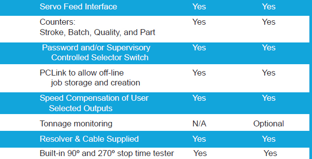
• Four Counters: Strokes, Parts, Batch, and Quality.
• Built‑in power supply for input sensors (+12VDC).
• Built‑in servo feed interface.
• Crank shaft angle displayed in degrees with a
graphic shaft angle clock.
• Utilizes surface mount technology.
• Job memory chips are socketed for easy transfer to
other units if desired.
• Programmable minimum and maximum speed limits
with captive contact safety relay output (Form B
safety).
• Programmable variable speed compensation.
• Punch press clutch/brake timing signals protected
from tampering.
• Optional peak tonnage monitoring up to 4 channels.
• Compact in size.
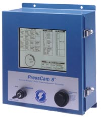
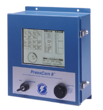
A large 8″ (203mm) diagonal LCD computer screen is standard equipment on the PressCam 8. This single component brings the intelligence of the dual computer system to the punch press control panel providing positive system status interaction with the machine operator. The screen brightness (contrast) is also adjustable so it can be easily read even when installed in dark areas.
This innovative device replaces keypads or keyboards for programming the PressCam 8. The programming knob works similar to a computer mouse. Simply turn the knob to the highlighted field or program you desire then push. Your program is accessed with no keystrokes. By turning the knob, the appropriate numbers or letters appear on the highlighted screen to program the specific function you desire. Push again, your programming is completed! Additionally, no information can be programmed if it is not applicable to the specific function or operation.
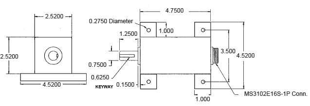
 The heavy duty brushless resolver transducer replaces the current mechanical rotary cam switch. This unit was designed for hostile industrial environments such as punch press mechanical shock and vibration, extreme temperature and humidity, oil, coolant and lubrication mists. The resolver transducer features excellent repeatability and gives absolute shaft position feedback. High speed operation along with long transducer cable (runs up to 600 feet/183m) give the resolver wide application ranges. The resolver is a passive device which contains no sensitive electronics and has superb noise immunity.
The resolver mounts easily to an end of a crankshaft and can rotate clockwise or counter-clockwise. Simple connector ended transducer cabling is supplied to connect the resolver to the PressCam 8 controller console. The PressCam’s microprocessor-based control constantly monitors the resolver position and displays both the angular position of the shaft and speed of the machine (tachometer). 3/4” (19 mm) resolver shaft diameter.
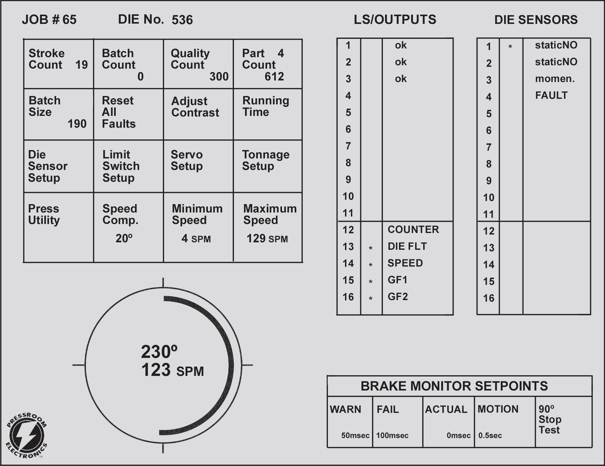
Shown above is the actual screen size and information available to the press operator on the PressCam 8 Programming Screen. No longer is it necessary to scroll through various menus and programming techniques to view
data. The Programming Screen also provides an active “tool bar” for your press set‑up personnel to quickly access the specific function they so desire. As one can see, a tremendous amount of production data can be obtained by simply viewing this single operator screen.
System simplicity is a dominant feature of the PressCam 8. By viewing the above screen, information can be obtained for four different counters, reset all faults, adjustment for screen contrast, die protection information, programmable limit switch information, shaft angle displayed in degrees, stroke per minute (SPM), and brake monitoring information.
Additionally, system fault messages are displayed in the area above the brake monitor setpoint section when they occur.

The Die Protection Screen shown above is what your programmer will see when entering the die protection program. PressCam 8 provides sixteen different die protection sensor inputs that may be programmed for both cyclic and/or static function monitoring. Cyclic function monitoring requires that an input sensor signal occur within a certain programmed shaft angle on each press cycle (e.g., part eject, part transfer). Static monitoring is used for non‑cyclic events such as end of material or stock buckle monitoring. A fault output will occur if an input transition is not detected between the programmed limit set points (e.g., a part is to be ejected out of the die between 190º and 250º of the machine cycle). If the part is not detected within these parameters, a fault or stop signal is given to stop the machine.
To program, simply turn to “die‑sensor set‑up” and depress the programming knob. Now you are in the die protection program. Then put in the parameters in degrees when you would want to look for the part to eject
or transfer. From 190º to 250º is when the sensor will be looking for the part. That is all there is to programming
die protection. If a fault output occurs, simply view the screen and determine from what sensor the fault occurred.
 The die protection program can be fine tuned while the machine is in motion along with related peripheral signals
such as feeds, lubrication, blowoffs, etc. This is an excellent method of increasing the machines efficiency.
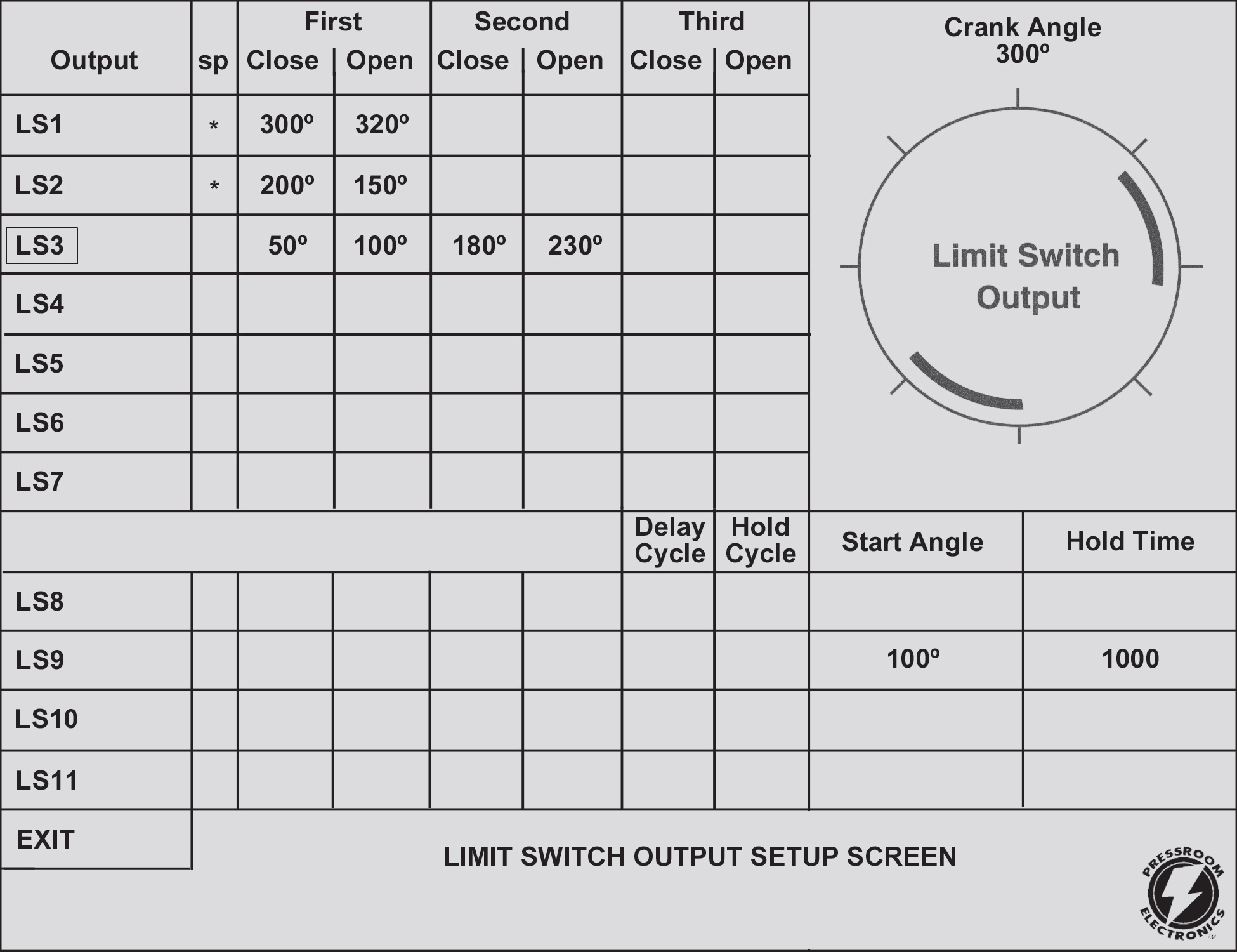
Limit switch programming simplicity is a PressCam 8 feature. PressCam 8 crank angle position is generated by a heavy duty industrial resolver driven by the press crank shaft. PressCam 8 provides the user with eleven programmable limit switch outputs used to initiate various peripheral equipment. These outputs can be programmed to turn on and off up to three times per press cycle. The programmable limit switch outputs may be mechanical relay, solid state AC, or solid state DC. The solid state relays may be mixed on the same relay board. The Delay and Hold cycle feature provides control for lubrication systems, scrap choppers, etc. This provides you with signals when you need events to occur on a pre‑programmed intermittent (time) or multiple stroke basis. Limit switches 1 – 7 can be programmed to turn ON and OFF up to three times per press cycle. Limit switches 8 – 11 can be programmed to turn ON and OFF up to two times per press cycle or may be programmed to turn ON based on angle and OFF based on time. The timed outputs can be programmed from .001 to 10 seconds. Furthermore, these switches may be used with the Delay and Hold cycle feature which provides control for items that need not be initiated on every press cycle but a programmed number of press cycles. Or they can be held ON for a pre-programmed number of press cycles. A minimum and maximum speed limit setting can be used to monitor optimum running speed versus actual. A deviation outside the programmed parameters will initiate a stop signal. The system includes a true motion detection system that monitors the press cycle. If you tell the press cycle and it fails to move within the pre-programmed time (.001 to 4 seconds), a fault signal is issued. On the opposite side, if the press starts to cycle without initiation, a fault signal is issued to electrically disconnect all signals. The clutch/brake timing signals can also be password-protected from inadvertent tampering by unauthorized personnel.
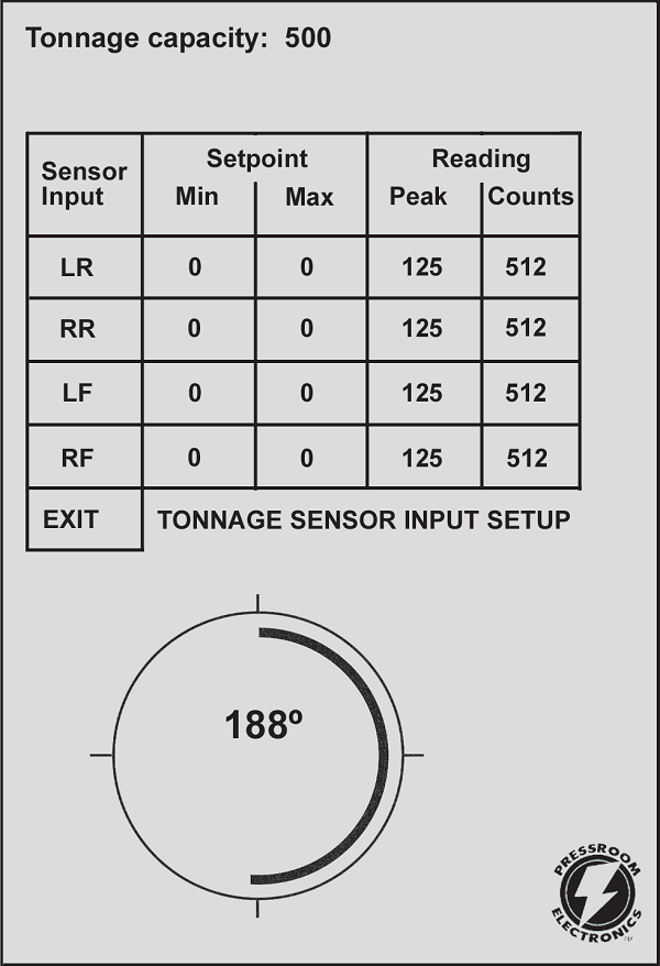
The TLM I/0 load module is designed for critical force measurement applications where accuracy, extreme stability,
and dependable noise rejection is essential. The module is a load measurement device without a display or alarms.
The TLM is used as an input device to the PressCam 8 providing display and alarm control functions. The TLM has high sensitivity levels that work well in an electrically “noisy” environment. It has two amplifier gain ranges (span ranges). Therefore, it can accept either weak or strong signals from the load sensor.
Features
• Signal conditioning module for strain gauge
sensors and load cells
• Four independent channels for accommodating
up to eight sensors
• For use with full‑bridge sensors from 120
Ohms to 1,000 Ohms
• Plug‑in connectors are used for the sensor
inputs
• High/low sensitivity span ranges selected
with front panel switch
• Automatic zero balance circuits assure accurate
measurements
• Power input/output are plug‑in connectors
• Built‑in automatic peak load memory circuits
• Peak measurements are made with an external
trigger device
• Built‑in power supply for stable operation
and noise rejection
• Compact size to fit almost any location
• Steel enclosure for maximum protection and
noise rejection
Transducers Full Bridge, 120 Ohms to 1,000 Ohms. One to
four channel version available. Maximum of two 350 Ohms
sensors per channel.
Dimensions 2″ (51mm) x 3.1″ (79mm) x 8.95″ (227mm)
Balance Range +/‑ 1 mV/V of offset
Gain ‑ Two Ranges Low = 100 to 1,100 adjustable
High = 1,000 to 11,000 adjustable
Output Range Approximately +/‑ 10VDC at 12VDC excitation
Circuit Accuracy Maximum inaccuracy of +/‑ 1% of full scale
Circuit Linearity Maximum non‑linearity +/‑ .1% of full scale
Auto Zero Time Constant 10 seconds
Frequency Response Flat DC to 1 KHz
Peak Decay Less than 1% of full scale in 10 minutes
Calibration Shunts 1 Meg Ohm, .1%
Input Power 100 to 130VAC 50‑60 Hz. Fused at .10 Amp.
200 to 260VAC 50‑60 Hz. Fused at .05 Amp.
Input is jumper selectable. Fuses are 5mm x
20mm SLO‑BLO.
Sensor Excitation Internally excited at +12VDC, .30 Amps
maximum
Sensor Input Connections Four pin .2” (5mm) centers
Phoenix connector
Peak Output Connections Six pin .2″ (5mm) centers
Phoenix connector
Proximity Probe 12VDC internally supplied to drive NPN
or PNP probes, 50mA max. Input also supports dry relay
contacts.
Set Points:
Stroke Count: 0 to 999,999 strokes
Batch Count: 0 to 999,999 strokes
Quality Count: 0 to 999,999 parts
Part Count: 1 to 4 parts/strokes (programmable)
0 to 999,999 parts total
Batch Size: 0 to 999,999 parts
Limit Switch Angle: 0 to 359 degrees
Limit Switch Timers: 0 to 9999 milliseconds
Die Sensor Angle: 0 to 359 degrees
Minimum Speed: 0 to 300 SPM
Maximum Speed: 0 to 300 SPM
Brake Warning: 1 to 999 milliseconds
Brake Failure: 1 to 999 milliseconds
Brake Actual: 1 to 999 milliseconds (+/‑ 1 ms accuracy)
Start Motion: 0 to 5.9 seconds (1/10 sec increments)
Crank Angle: 0 to 359 degrees (1 degree increments)
SPM: 0 to 300 strokes/minute (+/‑ 1 SPM accuracy)
Components: • PressCam 8 Master Controller Panel Mount
10.8″ (274mm) W x 11.8″ (300mm ) H x 2.5″ (64mm ) D
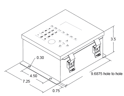
• PressCam 8 Master Controller mounted in a Stand Alone NEMA 12 Enclosure
11″ (279mm) W x 13.1″ (333mm) H x 5″ (127mm) D
• Resolver Transducer
+/‑ 1º Resolution up to 700 RPM
+/‑ 2º Resolution from 701‑1000 RPM
3/4″ (19mm) keyed shaft
Rated shaft loading: 200 lbs. axial 400 lbs. radial
Weight: 4 lbs. Shock: 200 G for 11 msec
Vibration: 20g to 2000 Hz Operating Temp: ‑20º to 125ºC
Enclosure: NEMA 13 Transducer to master controller: 600′ (183m) max
Rotation: CW or CCW Resolver Cable: 30’ (9m) supplied standard with
connectors
Diagnostics: Complete system diagnostics on LCD screen
Enclosure 18 gauge painted steel NEMA 12 lockable enclosure with sealed front panel or
Construction: open frame for panel mounting.
PressCam 8 is a “control reliable” resolver based programmable cam switch, time-based brake monitor, die protection system, multiple counters, and much more in one package. The system contains two 16-bit computers that are configured to cross check each other and the resolver. The dual computers are interfaced with a full view 8″ (203mm) diagonal LCD computer screen for viewing and programming ease. This large operator screen supplies operators and front line supervisors production data without the need of cumbersome menu and program access
codes.
(For Custom Programming & Remote Field Upgrades, please consult factory at service@pressroomelectronics.com or (630) 443-9320.)
PressCam 8 (all styles, Front panel & Stand alone). Includes resolver and cable
ORDERING PROCEDURE
1. Specify Mounting Style
F ……… Front Panel Mounting to be installed in an existing control panel.
C ……… Stand alone NEMA12 enclosure
T ………. Stand alone NEMA12 enclosure with room for the Tonnage Module
2. Specify Output Relays (11 maximum)
M ……… Mechanical Dry contact relays SPDT 10A@250VAC
A ……… AC Solid State – single Pole N.O. 3A@140VAC, 12-140VAC, 25-70Hz
D ………. DC Solid State – single Pole N.O. 3A@60VDC, 12-60VDC
3. Specify Controller Input power
1 ………. 24VDC
2 ………. 120VAC 50-60Hz
3 ……….. 240VAC 50-60Hz
4. Specify Clutch/Brake Valve Voltage
1 ………. 24VDC
2 ………. 120VAC 50-60Hz
5. Resolver Connector Cabling
30’ (9m) of cable with connectors is supplied standard. If additional length is needed, specify in
feet, 150’ (46m) maximum.
6. Specify Tonnage Monitoring (optional)
T1 ……… One Channel monitoring with strain sensor and cable
T2 ……… Two Channel monitoring with strain sensor and cable
T3 ……… Three Channel monitoring with strain sensor and cable
T4 ……… Four Channel monitoring with strain sensor and cable

TONNAGE MONITORING (OPTIONAL)
T1 One channel monitor module with strain sensor and cable
T2 Two channel monitor module with strain sensor and cable
T3 Three channel monitor module with strain sensor and cable
T4 Four channel monitor module with strain sensor and cable
Part
Number Description
30-012 24vdc @ 2.2A power supply (90-260vac In) 3.9” L x 3.8” W x 1.4” H (99.1mm x 96.5mm x 35.6mm)
for powering die protection sensors or other auxiliary devices.
Part
Number Description
11-131 Panel Mount (with gasket)
11-132 LCD mounting bracket (blue)
11-133 Aluminum Shield cover for computer board
11-134 Metal Box enclosure (with gasket)
11-135 Solid State Relay hold-down for I/O board
11-159 Large Metal Box enclosure (includes space for TTLM module)
18-005 B/W LCD display panel (with backlight)
18-006 LCD Backlight power supply
18-007 LCD Backlight fluorescent tube
20-022 1A Slo-Blo nano SMF fuse
20-023 5A Fuse (white nano)
21-047 Tuning Knob (black knob)
21-048 Tuning Knob (black ring)
26-071 Graphic overlay skin
30-009 Replacement Tonnage Controller (3 or 4 channel input unit)
30-010 Replacement Tonnage Sensors & 35’ of cable
30-013 Replacement Tonnage Controller (1 or 2 channel input unit)
32-038 Output Module (Solid State AC)
32-039 Output Module (Solid State DC)
32-041 Output Relay (G2R-1-S)
32-101 4 pole 12 VDC (clear KACO safety relay)
35-065 EEPROM JOB memory chip (50 jobs) (2 chips are required for 100 jobs)
(2 chips are required for 100 jobs)
39-051 RUN/PROG Keyswitch (with keys and cable)
40-002 Tuning Encoder device
45-019 LCD cable (from LCD to Computer board)
45-020 Resolver cable (30’) with connectors
52-115 Power & I/O board (without output modules) specify solid-state or relay
52-116 Dual Computer board (with 100 job memory)
52-122 I/O ribbon cable (from I/O board to Computer board) 2’
52-123 Power cable (from I/O board to Computer board) 2’
52-227 Resolver unit (no cable) (formerly 40-003)
52-282 Serial to Ethernet Board for PressCam 8
PressCam 8 Junior shown
installed in a stand alone
NEMA 12 (IP64) lockable
enclosure
PressCam 8 Junior
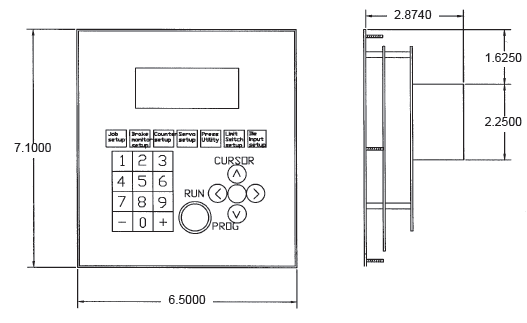
Front Panel Mount
Cut-Out Dimensions
Resolver Transducer

Click here: Installation Manuals
Click here: Literature
Click here: Contact Sales
Click here: Contact Service