Introduction
A press cycles, a conveyor stalls, a clutch fails to engage. Every one of those problems lives somewhere along the same signal path: something senses a condition, something decides, and something acts. If you can't picture that path, troubleshooting turns into guesswork.
This guide is for maintenance teams, plant engineers, press rebuilders, machinery OEMs, and industrial distributors in US manufacturing. It covers the three core components, feedback, open-loop and closed-loop control, and the PLC, SCADA, and DCS architectures. A metal stamping example runs through it.
Key Takeaways
- Sensors supply information, controllers apply logic, and actuators do the physical work.
- Feedback, HMI, communications, power, and safety devices complete an industrial system.
- Open-loop and closed-loop describe feedback behavior; PLC, SCADA, and DCS describe architecture.
- Choose components around the process, feedback, safety, environment, and future expansion.
What Is a Control System?
A control system is a coordinated group of hardware, software, and programmed logic that monitors conditions and directs a machine or process toward a desired result. NIST's guide describes it as deliberate guidance or manipulation of a variable to reach a prescribed value.
Basic control-system terms
- Setpoint: the desired value of the controlled variable, set manually, automatically, or by program
- Input signal: the measurement or command entering the controller
- Plant (controlled process): the physical equipment performing the process
- Output: the actual result the process produces
- Feedback: measured output returned for comparison with the reference
- Error: reference minus measured output
- Disturbance: an outside influence on the output, such as a load change
A motor shows how these fit. You set a speed of 1,000 RPM, a sensor reads actual speed, and the difference is the error. Add load torque and that is your disturbance. On a punch press, the setpoint might be a stroke rate in strokes per minute (SPM).
Why the components must work together
A control system is more than a controller. The controller needs trustworthy input, the actuator needs enough energy to act, and the process needs to respond as expected. A bad resolver signal, a loose terminal, or a failed output relay produces the same symptom: the machine won't do what it was told.
The Core Components of a Control System
The common "three main components" answer is the sensor, controller, and actuator. Some engineering models split out additional blocks such as the comparator, feedback path, input, and plant. NIST's list also includes communication, so treat the three as primary functions rather than a complete parts list.
Sensor or sensing element
Sensors and transducers convert a measurable condition into a signal the controller can read. Typical conditions include position, speed, pressure, temperature, proximity, and force.
- Proximity sensors: Detect objects without contact; OMRON describes inductive types for metal and capacitive types for metallic and nonmetallic objects
- Rotary encoders: Convert rotation into electrical position or speed information
- Resolvers: Provide rugged position sensing; the Pressroom Electronics brushless resolver gives absolute crankshaft position and is passive, with no sensitive electronics
- Pressure switches: Monitor a threshold, such as air-supply pressure adjustable from 1 to 115 PSI
Controller or decision-making element
The controller receives inputs, applies logic or an algorithm, and sends commands. When feedback exists, it compares conditions with the desired state.
Implementations range from relay logic and PLCs to motion controllers and specialized machine controls. A press control, for instance, may read crank angle, check speed limits, and decide whether to allow the next stroke.
Actuator or final control element
Actuators turn an electrical command into mechanical work. They start motors, move cylinders, open valves, and engage or release a clutch or brake. The command is a low-power signal; the actuator delivers the force. A dual solenoid valve, for example, takes a controller signal and admits air to a clutch.
Feedback and comparison
Feedback returns actual output to the controller so it can find the error and correct it. It is often treated as its own block even though it usually depends on a sensor. Without it, the controller is only assuming the output happened.

Supporting components in an industrial system
Around the core three sit the pieces that make a system work in a plant:
- The controlled machine itself
- HMI and operator stations
- Communication networks such as Ethernet or CAN
- Power supplies, circuit protection, and wiring
- Safety interlocks, guards, and emergency stops
- Alarms and data logging
How Control Systems Work
The basic sequence runs in five steps:
- An operator or program sets a desired condition.
- Sensors measure the process.
- The controller interprets the signals.
- The actuator changes the machine's state.
- Feedback confirms whether the result is right.
Open-loop control
An open-loop system issues a command without using the output to correct itself. A timed operation, such as a lubrication pulse or a micro-inch jog that moves the ram for a preset time, is a good example.
This works when conditions are predictable. When load or wear changes, the output drifts and nothing notices.
Closed-loop control
A closed-loop system measures the result, compares it with the setpoint, and adjusts. In an Illinois ECE 486 example, a DC motor tracks its reference speed despite load torque, while the open-loop version develops a speed offset. Position, speed, temperature, and pressure regulation all rely on this approach.
The role of disturbances and error
Material variation, wear, vibration, temperature swings, and load changes push a process off target. Feedback with suitable control logic reduces their effect. Sensors themselves can drift between calibrations, so feedback is only as good as the measurement behind it.
Safety functions and interlocks
Safety circuits, guards, emergency stops, brake monitoring, and access interlocks can stop or inhibit motion independent of production logic. That separation matters: safety functions protect people and equipment even when the production cycle is otherwise valid.
For mechanical power presses, OSHA 29 CFR 1910.217 applies, and applicability depends on the machine and safeguarding method. Check the current text and your press type before specifying anything.
A simple machine-cycle example
On a part-revolution press, a cycle runs like this:
- The operator presses both run buttons.
- The controller verifies inputs, speed, and guarding status.
- It energizes the clutch valve; the crankshaft turns.
- A resolver reports crank angle, and limit-switch outputs fire at set angles.
- At top stop, the brake engages and the controller checks stopping time.
- Any fault blocks the next stroke.

Break any link in that path and the fault shows up differently:
- A missing die-sensor signal gives a no-start
- A marginal brake reading causes a nuisance stop
- A resolver cable fault can look like a motion fault
Knowing the path tells you where to measure first.
Common Types of Control Systems
Industrial control is often split into three architectures, but that label depends on context. PLC, SCADA, and DCS are the ones plants discuss most. Open-loop and closed-loop describe feedback behavior, so they aren't competing choices. NIST notes that PLCs also operate within SCADA and DCS, so the categories overlap.
| Architecture | Role | Typical use |
|---|---|---|
| PLC | Local programmable logic, I/O, timing, counting | Presses, conveyors, assembly machines |
| SCADA | Supervision, visualization, alarms, data from dispersed assets | Pipelines, water systems |
| DCS | Coordinated controllers across a production site | Refineries, chemical processing |
PLC-based control systems
PLCs are rugged programmable controllers suited to discrete, sequential, repetitive work. Input modules read sensors, the program runs, and output modules drive actuators. IEC 61131-3:2025 covers PLC languages such as ladder diagram and structured text.
SCADA systems
SCADA handles supervision: visualization, alarms, and data collection, sometimes across many sites. Lower-level controllers still run direct machine control. A PLC runs a machine; SCADA watches many of them.
Distributed control systems
A DCS spreads control across multiple controllers for larger or continuous processes, with coordinated operator supervision. It suits a refinery better than a single press, but neither architecture is universally better.
Other useful classifications
- Discrete versus continuous processes
- Manual versus automatic control
- On-off versus proportional control (proportional-only control can leave an offset)
These categories overlap, so don't treat them as one master list.
Applying Control System Components to Metal Stamping
The same control-system model maps directly onto a mechanical punch press:
- Input: operator or production command
- Sensing: resolver or rotary-cam position, die sensors
- Decision: press control logic
- Actuation: clutch/brake or motor
- Support and safety: brake monitoring, die protection, guarding
Selecting components for a press or machine retrofit
Work through this checklist:
- Machine type and age
- Required inputs and outputs
- Cycle speed
- Resolver or rotary-cam feedback needs
- Clutch/brake requirements
- Panel space and environment (oil, coolant, heat)
- Communications and diagnostics
- Safety functions
- Compatibility with existing equipment
Keep requirements and selection factors separate. Under OSHA 1910.217(a)(4), modifying a mechanical press means meeting paragraph (b). Preferences like diagnostics are choices, not mandates.
Pressroom Electronics solution placement
Pressroom Electronics manufactures pressroom electronic controls and automation for metal stamping and forming. The lineup covers customized clutch/brake controls, resolver- and rotary-cam-based applications, brake monitoring, die protection, guarding, and production monitoring.

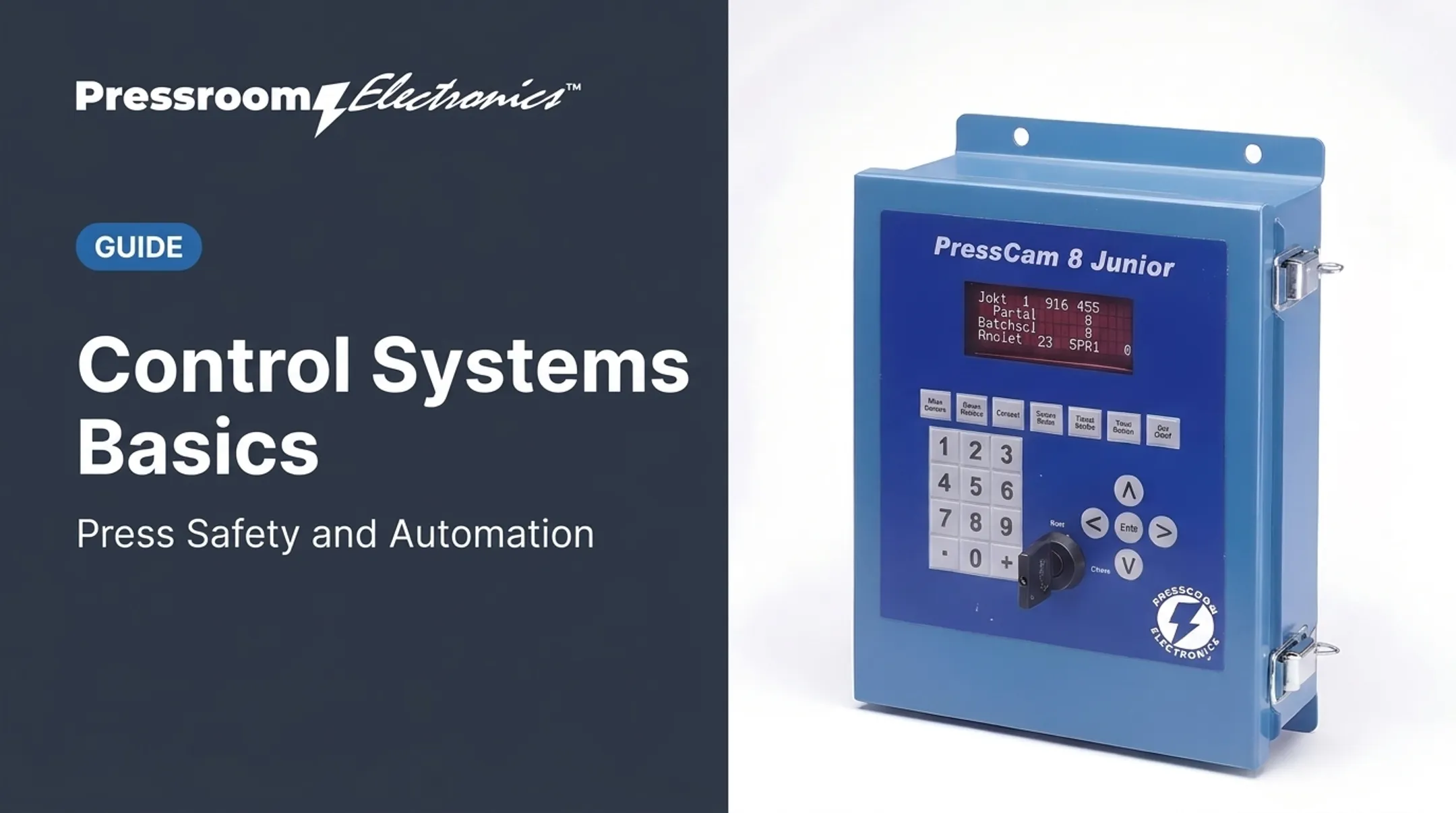
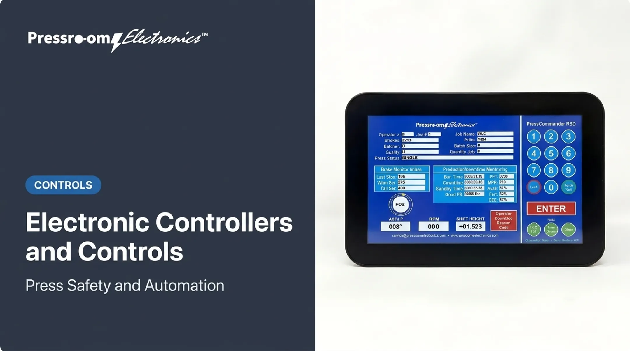
PressCommander is designed to exceed OSHA 1910.217 and ANSI B11.1-2009 (R2020). PressCam 8 combines a programmable cam limit switch, brake monitor, counters, and die protection. Factory-created programming and remote field upgrades are available as options.
If you're planning a retrofit or rebuild, contact Pressroom Electronics at sales@pressroomelectronics.com or 800-937-4334 to talk through your application.
Frequently Asked Questions
What are the three main components of a control system?
Sensor, controller, and actuator. A complete industrial system may also need feedback, the controlled process, HMI, communications, power, and safety equipment.
What are the three main types of control systems?
In industrial architecture, PLC, SCADA, and DCS are the usual grouping. Open-loop and closed-loop describe feedback behavior, a different kind of classification.
What is the difference between an open-loop and closed-loop control system?
Open-loop systems issue commands without using output feedback to correct. Closed-loop systems measure the result and adjust based on error.
What does a PLC do in a control system?
A PLC reads inputs, executes programmed logic, and controls outputs. Those outputs drive devices such as motors, valves, and machine actuators.
How do you choose control system components for a machine?
Start with process requirements, I/O, feedback method, actuator load, and safety functions. Then consider environment, communications, retrofit compatibility, and future expansion.