Resolvers earn their place on machines that are hot, dirty, oily, shaky, or electrically noisy. They are passive, sturdy, and have no optical disk to foul. But the sensor is only part of the story: excitation, cabling, the converter, and calibration all have to work together.
This guide covers what a resolver is, how its sine and cosine signals work, how it compares with encoders and synchros, and how to select and troubleshoot one.
Key Takeaways
- A resolver is an electromechanical rotary sensor that sends analog sine and cosine signals to a controller.
- The controller derives angle, then speed and direction, for closed-loop control.
- Treat the sensor, wiring, excitation, converter, and calibration as one system.
- Choose based on drive, environment, mechanical fit, signal needs, and maintenance skills.
What Is a Resolver Sensor for Motors?
A resolver is a rotary transformer that measures shaft angle through electromagnetic coupling. Its output amplitude varies sinusoidally with rotation, according to AMCI's tutorial.
What a resolver contains
A conventional control-transmitter resolver has:
- A rotor carrying the reference (excitation) winding, coupled mechanically to the motor shaft
- A stator with sine and cosine windings displaced 90 degrees
- A rotary transformer in brushless wound-rotor designs that energizes the rotor without brushes or slip rings
Variable-reluctance designs differ: both windings sit on the stator, and a salient rotor changes the coupling.
The bare sensor is not the whole feedback system. Excitation drivers, signal conditioning, a resolver-to-digital converter (RDC), and drive software handle the rest.
What the sensor tells the controller
The two phase-shifted outputs together encode shaft angle. The controller uses that angle for commutation, torque production, speed regulation, direction detection, and stopping at a commanded position.
Why motors use resolvers
There are no optical markings to contaminate, so resolvers suit harsh or noisy machinery. Ratings are product-specific, not universal claims.
Pressroom Electronics, for example, describes its heavy-duty brushless resolver transducer as passive, with no sensitive electronics. It is built for punch-press conditions such as:
- Shock and vibration
- Temperature extremes
- Humidity, oil, coolant, and lubrication mist
How Does a Resolver Work in a Motor Feedback System?
The signal path runs in a loop: the controller sends an AC excitation signal to the resolver, the sine and cosine outputs return, and the controller's position circuitry turns them into an angle.

Resolver excitation
The controller drives the excitation winding with an AC reference. Voltage, frequency, loading, and waveform quality must match both the resolver and the interface. Documented examples vary widely:
| Resolver | Excitation | Transformation ratio |
|---|---|---|
| Moog CD standard two-pole | 4 Vrms, 3.4 kHz | 0.5 ±10% |
| Tamagawa TS2610N171E64 | 7 Vrms, 10 kHz | 0.5 ±5% |
| Tamagawa TS2620N271E14 | 10 Vrms, 4.5 kHz | 0.5 ±5% |
These are model-specific, not universal limits. Wrong excitation or loading produces bad feedback even when the mechanics are fine.
Sine and cosine generation
Rotation changes the magnetic coupling between rotor and stator. Analog Devices gives the outputs as E0*sin(θ)*sin(ωt) and E0*cos(θ)*sin(ωt): AC carriers whose amplitudes follow the sine and cosine of shaft angle. The 90-degree displacement lets the controller resolve a unique angle.
Resolver-to-digital conversion
An RDC demodulates the analog signals and calculates the angle. The AD2S1210, for instance, offers 10- to 16-bit conversion and signed velocity output. Converter resolution is not sensor accuracy; phase error and channel-amplitude mismatch limit accuracy.
Good conditioning means differential inputs, shielding, filtering, and a resolver and controller that are compatible. Inverter switching can induce shield currents that couple into signal pairs, as Texas Instruments documents.
Position, speed, direction, and commutation
Successive angle readings give speed and direction. The instantaneous angle drives commutation and torque control. A position error or intermittent signal can show up as:
- Speed fluctuation or vibration
- Loss of torque
- Overcurrent faults
- Poor stopping accuracy
Calibration and zero-angle alignment
The resolver's zero must line up with the motor's electrical position. Beckhoff's AX5000 drive, for example, determines and stores a commutation offset. Separate calibration error from mechanical misalignment, wiring faults, controller faults, and motor-phase problems before changing anything.
Why Use Resolver Sensors in Industrial Motors?
Resolvers trade electronics complexity for ruggedness. Here is where that trade pays off.
Reliability in demanding environments
Published ratings show the range, though test conditions differ:
| Product | Temperature | Shock | Vibration |
|---|---|---|---|
| Tamagawa Smartsyn (built-in) | -55 to +155 °C | 100 G, 6 ms | 20 G, 10-500 Hz |
| Honeywell Hawk 3-Inch | -50.8 to +93.3 °C | 50 g, 11 ms | 15 g, 10-2,000 Hz |
| AMCI HT-20 | -40 to +125 °C | 50 G, 11 ms | 15 g to 2,000 Hz |

The whole installation matters: housing, bearings, connectors, cable routing, shielding, grounding, and mounting. AMCI offers optional IP67 on named HT-20 variants, which shows ingress protection comes from the enclosure, not the sensing principle.
Motor-control performance
Accurate rotor position supports:
- Stable speed and torque regulation
- Clean direction changes and controlled stops
- Repeatable cycles across production runs
- Earlier flags on abnormal motion for maintenance decisions
Industrial applications
- Servo systems and machine tools (Moog brushless resolvers)
- Welding robots and injection-molding machines (Tamagawa)
- Hybrid and electric vehicle powertrains (Texas Instruments)
- Packaging lines and stamping presses (AMCI)
The application sets the accuracy, response, speed range, durability, and interface you need.
Resolver feedback in pressroom control systems
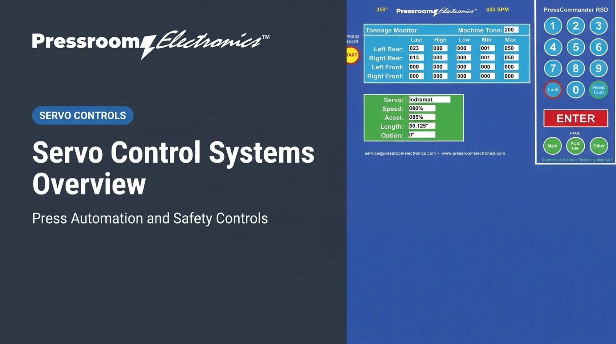
On punch presses, crankshaft position drives coordinated machine operation. Pressroom Electronics builds resolver-based clutch/brake controls and customized punch press control applications for metal stamping and forming. The PressCam 8 Junior reads crank angle from 0 to 359 degrees at 1-degree resolution and speed from 0 to 999 strokes per minute. Confirm PressCam details with Pressroom Electronics technical support before specifying.
Sensing is not protection. OSHA 1910.217 sets brake-monitor requirements for certain part-revolution-clutch press arrangements, and stopping performance is a separate function from position feedback.
Limitations and tradeoffs
- Resolvers need excitation and signal-processing electronics; many encoders output digital data directly
- Analog signals demand careful wiring and noise control
- Calibration and commissioning need qualified people
- Confirm controller compatibility up front
Resolver Sensors vs. Encoders, Synchros, and Other Types
Resolvers and encoders
| Factor | Single-turn resolver | Incremental encoder | Absolute encoder |
|---|---|---|---|
| Output | Analog AC sine/cosine | Pulses | Unique position codes |
| Position after power loss | Reported within one turn | Relative to reference | Reported (single/multi-turn) |
| Processing | Needs RDC or compatible drive | Direct digital counting | Digital interface |
Environmental tolerance varies by model. Moog's CD motor catalog rates resolver-equipped motors for Class F 155 °C against encoder maxima near 110 °C, but that applies to that motor family only. Neither technology wins everywhere.
Integrated products like AMCI's resolver-based encoder combine resolver sensing with digital outputs, so they are not the bare analog sensor.
Synchros and resolvers
Both are rotary transformers. A synchro transmitter has a single-phase rotor and three-phase Y-connected stator, while a resolver uses two-phase windings. Manufacturers' terminology varies.
Resolver types
- Brushless wound-rotor: rotary-transformer excitation, no brushes or slip rings
- Variable-reluctance (Singlsyn): no rotor coil; shaped rotor modulates amplitude
- Transmitter / control transmitter: reference plus sine/cosine winding configuration
- Control transformer: resolver used as a CT stage in control loops
- Single-speed (1X): one electrical cycle per revolution
- Multispeed (nX): several cycles per revolution; absolute only within one electrical cycle
Winding type and speed factor are different attributes. Verify any choice against the motor documentation, excitation, output, shaft interface, accuracy, speed range, and drive input.
How to Select and Troubleshoot a Motor Resolver
Specification checklist
- Motor and shaft compatibility, mounting dimensions, shaft or bore style
- Allowable speed and angular accuracy
- Temperature range, shock, vibration, oil and moisture exposure
- Connector and cable requirements
- Excitation, output signals, and controller interface
Tamagawa's size designations (06, 08, 10, 15, 21, 34) show how much variation exists even within one family.
Selection and integration
Select the resolver and drive as a matched pair. Check excitation settings, differential wiring, shielding, grounding, and the controller's approved pinout. Wire with shielded twisted pairs, run resolver cable away from high-current lines or in its own conduit, keep a 1:1 ratio on any chain or belt drive, and use a separate earth-ground conductor.
Record the resolver model, wiring diagram, calibration procedure, motor data, and settings before commissioning or replacing anything.
Troubleshooting workflow
- Review drive fault codes and operating conditions
- Inspect connectors and cables for damage
- Verify mounting and coupling
- Confirm excitation
- Check sine/cosine quality with approved test equipment
Likely causes include reversed or open signal pairs, poor shielding, intermittent continuity, wrong phase relationships, misalignment, and failed controller inputs. The AD2S1210, for example, flags disconnected inputs, clipping, amplitude mismatch, and lost tracking.

On Pressroom Electronics controls, typical faults include an angle mismatch between master and slave boards, or a "moving backwards" fault that points to resolver wiring.
Safety: Follow lockout/tagout under OSHA 1910.147, use the manufacturer's pinout, and let qualified personnel do the work. Don't rely on generic resistance or voltage limits. Use the documentation for your specific resolver and controller.
Maintenance and replacement
Rule out motor windings, drive, controller, grounding, and mechanical load before replacing the sensor. After a repair, recalibrate, verify across the full operating range, and document final settings. Recurring faults often point to a root cause elsewhere in the system.
Frequently Asked Questions
What is a resolver sensor?
A resolver sensor is an electromechanical rotary position sensor. It uses AC excitation and sine/cosine outputs to report shaft angle to a motor-control system.
What is a resolver sensor used for?
Resolvers provide motor position feedback for speed and direction calculation, commutation, and torque control, often in demanding industrial equipment.
How does a resolver sensor work?
AC excitation couples electromagnetically from rotor to stator. The sine and cosine outputs vary with shaft angle, and the controller converts them into position.
What is the difference between a resolver sensor and an encoder?
A resolver gives analog AC signals that need an RDC or compatible drive. Encoders typically output digital pulses or codes. Environmental ratings and drive compatibility vary by model.
What is the difference between a synchro and a resolver sensor?
Both are rotary transformers. Synchros typically use a three-phase stator output, while resolvers use two-phase sine/cosine windings.
What are the types of resolver sensors?
Common types include brushless, variable-reluctance, transmitter, control-transformer, single-speed, and multispeed. Terminology varies by manufacturer.