Most problems in these systems trace back to one weak link. A worn seal, a clogged filter, or an undersized valve can pull down the whole machine. Knowing how the parts connect makes selection, troubleshooting, and safe service far easier.
This guide covers hydraulic and pneumatic systems, what each component does, how the operating sequence runs, and where each technology fits in practice.
Key Takeaways
- Hydraulics use liquids; pneumatics use compressed gas.
- The main path runs from prime mover to pump or compressor, through conductors and valves, to an actuator.
- Filters, reservoirs, accumulators, and sensors keep the system reliable and controllable.
- Size components around force, speed, pressure, flow, environment, and fluid compatibility.
What Is Fluid Power?
Fluid power transmits energy through a pressurized working medium instead of mechanical linkages. Pressure determines force. Flow determines speed. Resistance to flow is what builds pressure in the first place.
Hydraulic systems use a specified hydraulic fluid. Pneumatic systems use compressed air or another approved gas. The right choice depends on the equipment manufacturer's specification, temperature range, seal materials, lubrication needs, and safety requirements.
The Core Principles
Pascal's law says pressure applied to a confined liquid is transmitted undiminished in all directions. Two simple relationships follow from it:
- Force = Pressure × Area. F is force, P is pressure, and A is effective piston area. Pounds per square inch times square inches gives pounds-force.
- Speed = Flow ÷ Area. v is piston speed, Q is volumetric flow into the cylinder, and A is the same piston area. Units must be consistent.
Here is a lifting example. The National Fluid Power Association gives this case: 1,000 psi acting on a 2-inch piston (about 3.14 in² of area) produces roughly 3,140 lbf of force. To make that piston move faster, you add flow, not pressure.
NFPA also notes that hydraulics typically run at thousands of psi, while most pneumatics run at about 100 psi or less. These are typical ranges, not hard limits.
Fluid Power Components and Their Functions
Power Source, Pumps, and Compressors
An electric motor or engine is the prime mover. It supplies mechanical energy but doesn't move fluid itself. The pump or compressor it drives does that.
A hydraulic pump creates flow, and pressure develops when that flow meets resistance. A compressor raises the pressure of a gas. Common pump types include:
- Gear pumps for fixed displacement
- Piston pumps for variable-flow work
- Vane pumps for low-noise industrial applications
Reservoirs and Receivers
A hydraulic reservoir stores fluid and receives return flow. It also helps shed heat and lets contaminants settle. A pneumatic receiver stores compressed air so the system can meet demand spikes and hold pressure steady.

Conductors and Connection Hardware
Pipes, tubes, hoses, fittings, manifolds, and seals carry the working medium. Selection depends on:
- Pressure rating and surge pressure
- Temperature and vibration
- Bend radius and routing
- Compatibility of tube, cover, fittings, and seals
The lowest-rated part limits the pressure rating of the entire assembly.
Control Valves
Valves handle three primary jobs:
- Directional valves set the flow path
- Pressure valves (relief, reducing) limit or regulate pressure
- Flow valves set actuator speed
Check valves block reverse flow.
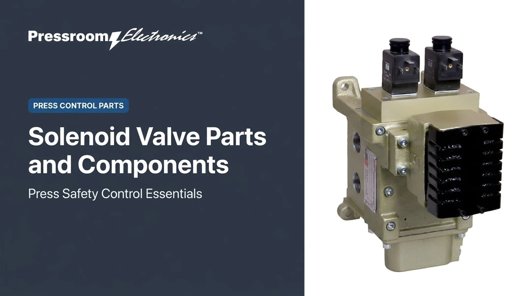
Actuation can be manual, mechanical, pneumatic, hydraulic, or solenoid-operated. Together, valves decide actuator direction, force, speed, sequencing, and overpressure protection.
Actuators
Cylinders produce linear force and travel. Motors produce rotary torque. Both turn fluid energy into useful work.
Conditioning and Monitoring
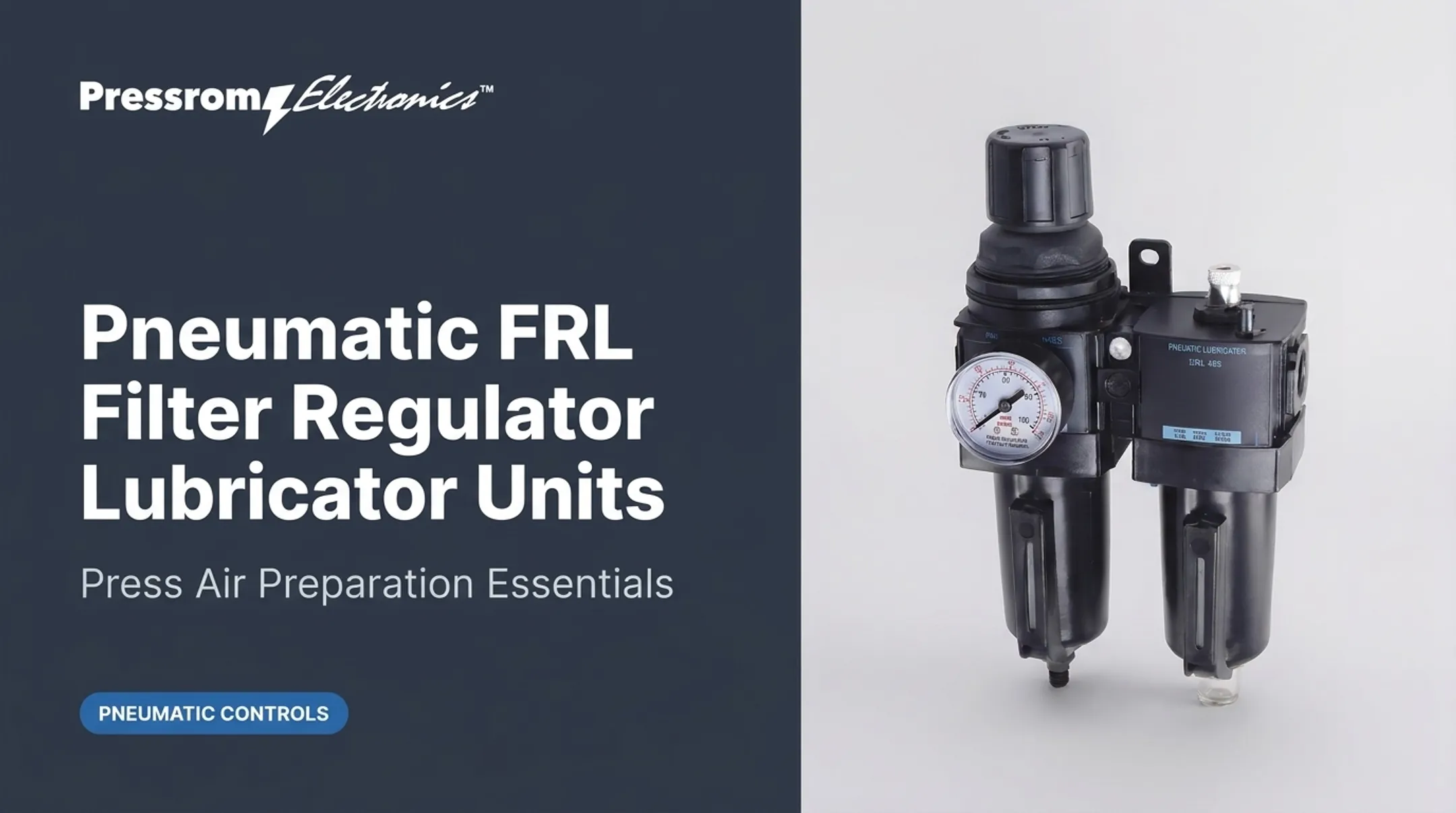
- Filters and strainers clean hydraulic oil and intake air
- Dryers remove moisture from compressed air
- Lubricators supply point-of-use lubrication when required
- Heat exchangers cool oil
- Accumulators store pressurized fluid, maintain pressure, and reduce shock
- Gauges and sensors track pressure, temperature, level, and position
Sensors make a system more observable. They don't replace correct sizing, cleanliness, installation, or maintenance.
How a Fluid Power System Works
Energy Generation and Fluid Movement
In a hydraulic system, the sequence runs prime mover, pump, conductors and valves, actuator, then return to the reservoir. The pump generates flow. Resistance downstream creates pressure.
Control and Distribution
Valves take commands from an operator or controller and send fluid to the right actuator. Pressure and flow controls regulate output. A relief valve caps pressure and handles spikes the pump can't respond to quickly enough.
Conversion Into Mechanical Work
Pressure on a piston makes linear force; flow into a motor makes torque. Extending and retracting differ. Extension acts on the full piston area, while retraction acts on piston area minus rod area, so retraction force is lower at equal pressure.
Feedback and Monitoring
Gauges and sensors measure pressure, temperature, position, and speed. Controllers use that data to adjust operation or flag abnormal conditions. Positioners, for example, use shaft feedback to match valve position to a setpoint.

Failure Points and Safe Service
Contamination is the usual culprit. Parker attributes over 75% of hydraulic and lubrication system failures to contamination, based on its field experience. Other common faults:
- Leaks and worn seals
- Trapped air
- Overheating
- Incorrect pressure or restricted flow
- Misaligned conductors or a failing pump
Before service, follow lockout/tagout under OSHA 1910.147. It covers hydraulic and pneumatic energy. You must relieve, disconnect, or restrain hazardous residual energy, address reaccumulation, and verify isolation before work.
Pinhole leaks are dangerous too. An OSHA accident report describes a tractor hydraulic leak that injected fluid into a worker's hand, requiring surgery. Always consult manufacturer documentation before service.
Hydraulic vs. Pneumatic Systems
| Dimension | Hydraulic | Pneumatic |
|---|---|---|
| Compressibility | Essentially incompressible | Air gives cushioning |
| Force density | Higher typical pressure | Larger actuator needed for equal force |
| Cleanliness | Return fluid recirculates; pressurized leaks can inject fluid | Needs filters and dryers for intake contamination and moisture |
| Heat | Oil may need heat exchangers | Most compressor electricity becomes heat |
| Storage | Accumulator | Air receiver |
The Department of Energy's compressed air sourcebook puts typical overall compressed-air efficiency at only 10-15%. That matters when comparing operating cost, not just purchase price.
Choosing Between the Two
Choose hydraulics for:
- Lifting, pressing, forming, and other heavy-duty work
- High force and controlled motion
Choose pneumatics for:
- Rapid reversal and simpler automation
- Lighter loads and clean operation
Performance depends on system design, not the medium alone. Evaluate duty cycle, force, speed, precision, available utilities, and operating conditions together.
Applications and Selection Considerations
Common Applications
| Sector | Typical technology |
|---|---|
| Manufacturing, machine tools, presses | Hydraulic |
| Metal forming (extrusion presses) | Hydraulic |
| Stamping clutch/brake controls | Pneumatic |
| Construction cranes, platforms | Hydraulic |
| Agriculture hitches, combine headers | Hydraulic |
| Forklift implements | Hydraulic |
| Automotive sheet-metal grippers | Pneumatic/vacuum |
| Aerospace (helicopter systems) | Hydraulic |
| Packaging, blow-molding valves | Pneumatic |
| Robotics end-of-arm grippers | Pneumatic |
| Process valve positioners | Pneumatic |
NFPA estimates that 2024 US fluid power component shipments reached $23.3B, with hydraulics at 76% and pneumatics at 24%.

Selection Checklist
Define these before choosing components:
- Load or force, stroke or rotation, and required speed
- Duty cycle, operating pressure, and flow demand
- Temperature, washdown chemicals, weld spatter, and side loads
- Fluid and seal compatibility (certain EPR seals, for example, are wrong for mineral oil)
- Contamination tolerance, available power, control method, space, and service access
Fluid Power in Pressrooms
Fluid power drives presses, forming equipment, and material handling, while electronics provide sequencing, status visibility, fault detection, and safety oversight. Classification matters: a pneumatic clutch/brake on a mechanical press does not make it a pneumatic power press, so OSHA 1910.217 still applies. Hydraulic and pneumatic power presses fall under ANSI B11.2.
Pressroom Electronics supplies press controls, automation, brake monitoring, die protection, guarding, and production monitoring for metal stamping and forming. It is a control and monitoring layer, not a supplier of hydraulic or pneumatic components. Its Model FPC control, for example, is built for hydraulic or pneumatic energy-based machines, with redundant microprocessors and monitored ram advance.
Frequently Asked Questions
What are the main components of a fluid power system?
A power source, pump or compressor, reservoir or receiver, conductors, valves, and actuators. Filtration, conditioning, and monitoring components support them.
How does a hydraulic power system work?
A prime mover drives a pump, which moves hydraulic fluid. Valves control direction, flow, and pressure, and an actuator converts the fluid energy into motion.
Which fluid is used in hydraulic power systems?
Systems use a specified hydraulic fluid, usually mineral oil, though water-glycol and other fire-resistant or biodegradable fluids exist. Always follow the equipment manufacturer's specification.
What are the two types of fluid power?
Hydraulics use liquids and typically run at higher pressure for heavy force. Pneumatics use compressed gas and suit fast, lighter-duty motion.
What are some examples of fluid power systems?
Hydraulic examples include presses, cranes, tractors, and forklifts. Pneumatic examples include packaging valves, robotic grippers, and press clutch/brake controls.
What are the fundamental principles of fluid power?
Pascal's law governs pressure transmission. Force equals pressure times area, and speed equals flow divided by area. Actuators convert fluid energy back into mechanical work.