Introduction
Electro-pneumatic control systems pair the decision-making and feedback of electrical controls with the force and fast actuation of compressed air. A PLC or relay decides, a solenoid valve routes air, and a cylinder or rotary actuator does the work.
The trouble is that correct logic doesn't guarantee good performance. Undersized valves, unstable pressure, leaks, a drifting sensor, or an unsafe failure state can all make a well-programmed machine run badly. Compressed-air leaks alone can waste 20-30% of compressor output in some plants, according to the US Department of Energy.
This guide covers definitions, signal flow, components, applications, benefits, limitations, selection, and troubleshooting.
Key Takeaways
- An electrical device (PLC, relay, sensor) controls pneumatic power through a solenoid-operated valve.
- The signal path runs from input to logic, solenoid, valve, air flow, actuator, and optional feedback.
- Suits repeatable push, pull, clamp, lift, eject, sort, and rotate tasks; weaker at continuous positioning.
- Reliability depends on sizing, clean regulated air, good feedback devices, and safe shutdown states.
What Are Electro-Pneumatic Control Systems and How Do They Work?
What is an electro-pneumatic control system?
"Pneumatic" means using compressed air or another gas to transmit power. The NFPA describes fluid power this way, with compressed air the usual medium. "Electro-pneumatic" adds electrical signals to operate those pneumatic components.
How it differs from the alternatives:
- Manual pneumatic: a person shifts the valve by hand.
- All-electric: motors supply the power, not air.
- Hydraulic: pressurized liquid supplies the power, usually for higher force.
In an electro-pneumatic system, air supplies the power and the electrical layer makes the decisions.
How does the electrical-to-pneumatic signal path operate?
A typical sequence looks like this:
- A sensor, switch, or operator command creates an input.
- A PLC or relay evaluates the logic.
- An output energizes a solenoid.
- The valve routes air.
- The actuator moves.
- Feedback confirms the move.
Feedback comes from proximity sensors, limit switches, pressure switches, or position sensors. Confirming an end position makes a system more controlled, but it doesn't automatically make it closed-loop. Many systems simply check "arrived" or "didn't arrive."
What role do PLCs, relays, and interlocks play?
Relays give simple, fixed logic. A PLC adds programmable sequencing, timing, diagnostics, and flexible I/O. Either one can enforce permissives and interlocks, which block motion until required conditions are met, such as a guard being closed.

Treat valve states as control design, not wiring detail. Decide up front:
- What the valve does when de-energized
- What happens on air loss or an emergency stop
- How stored pneumatic energy is released or held
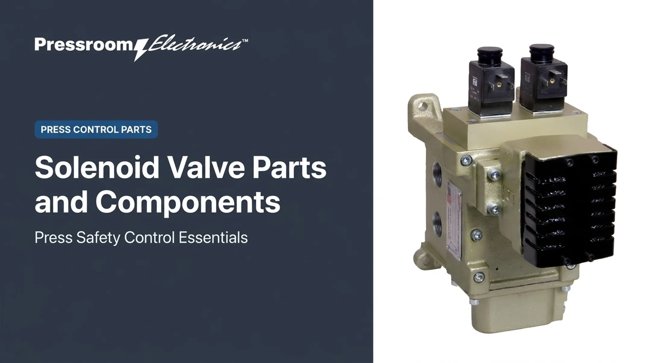
Pressroom Electronics, for example, builds dual-solenoid controls where each force-guided relay output drives its own valve coil, so either relay can shut the press down.
Key Components of an Electro-Pneumatic Control System
Air supply and preparation
The chain runs from compressor and receiver through a shutoff valve, filter, regulator, and sometimes a lubricator. Moisture, particles, oil carryover, and pressure swings all hurt valves and actuators.
- ISO 8573-1 defines purity classes for particles, water, and oil. Manufacturers specify the class they need; Festo, for instance, specifies 7.4.4 for its standard pneumatics.
- Filters and regulators add pressure drop, so keep downstream loss low.
- Many modern grease-lubricated components need no lubricator, and added oil can wash grease out.
- Size flow, pressure, and consumption from the machine duty cycle, not a generic catalog example.
Valves, solenoids, and flow controls
Directional control valves set direction. Designations such as 3/2 or 5/3 give port and position counts. Related devices handle the rest of the air path:
- Flow controls set speed
- Quick exhaust valves cut return time
- Check valves isolate circuits
- Mufflers manage exhaust noise
Check coil voltage and its permitted range, since out-of-range voltage can prevent shifting or burn out the coil. Also confirm flow rating, response time, and seal compatibility. Directional valves control direction only; pressure regulation is a separate function.
Actuators
Cylinders produce linear motion and rotary actuators produce angular motion. Single-acting versus double-acting describes how air is applied, not the motion type. Single-acting units return by spring or gravity.
Select on:
- Force or torque, stroke, and speed
- Cycle rate, mounting, and side loading
- Cushioning and operating environment
Ask what the load does if air pressure is lost.
Sensors and feedback
Proximity sensors, limit switches, pressure switches, transducers, and position sensors report part presence, end of stroke, pressure, or motion. Placement, wiring, response time, and correct PLC input setup prevent false confirmations and sequence faults.
Control hardware and communication
The control layer includes the PLC or relay panel, power supply, I/O modules, terminals, protective devices, HMI, and optional networking. Clear schematics, I/O labels, pneumatic diagrams, and alarm messages let maintenance isolate a fault to logic, output, valve, air supply, actuator, sensor, or mechanics.
Where Are Electro-Pneumatic Control Systems Used?
Common machine functions
| Function | Typical input | Action | Feedback |
|---|---|---|---|
| Clamping | Part-present sensor | Cylinder extends | Clamped-position switch |
| Ejecting | Cycle signal | Valve pulses cylinder | End-of-stroke sensor |
| Sorting | Vision or proximity | Diverter cylinder | Position sensor |
| Pick-and-place | PLC sequence | Linear plus rotary motion | Gripper and position switches |
Component choice shifts with load, speed, accuracy, and safety needs.
Metal stamping and forming
Pneumatic actuation supports auxiliary pressroom jobs: material handling, part ejection, clamping, and access equipment. Those are separate from the electronic logic controlling the press itself.
Clutch/brake circuits are the clearest case. OSHA 1910.217 requires controls to deactivate on loss of clutch air or counterbalance pressure.
Teams modernizing mechanical punch presses can evaluate press controls, brake monitoring, die protection, guarding, and production monitoring alongside any pneumatic actuation.
Pressroom Electronics makes these for stamping and forming, including controls for pneumatic and hydraulic machines. Verify compatibility with your specific press before choosing anything.
Pressure or variable control
An electro-pneumatic pressure regulator or proportional device beats a basic on/off valve when pressure must follow a recipe, load, or product. SMC lists press fitting, tension control, air balancers, and polishing as common applications.
For simple end-to-end strokes, on/off valves are enough. Electric or hydraulic motion fits better when you need fine positioning, very high force, or have no compressed-air infrastructure.

Benefits, Limitations, and Alternatives
Main benefits
- Repeatable sequencing through programmable logic
- Rapid actuation and compact components
- Strong force for most machine tasks
- Modular construction and familiar service procedures
- Visibility into recurring stops through PLC alarms and event histories
Be careful with downtime claims. One Festo field result on servo-pneumatic welding guns reported 22% less downtime for long malfunctions, but it combined diagnostics and condition monitoring, not alarms alone.
Limitations
- Compressed air is costly; DOE puts typical overall system efficiency at 10-15%
- Leaks, pressure variation, and moisture
- Exhaust noise and seal or valve wear
- Limited inherent positioning accuracy
- Need for both electrical and pneumatic skills
Poor air preparation or undersized tubing can look like an electrical or programming fault. Diagnose the whole system.
Comparison with other options
TiMOTION's qualitative ratings:
| Type | Force | Speed | Positioning | Efficiency |
|---|---|---|---|---|
| Pneumatic | Low | High | Low | Low |
| Hydraulic | High | Medium | Medium | Medium |
| Electric | Medium | High | High | High |
Electro-pneumatic control isn't automatically cheapest or most precise. The motion profile and conditions decide.
A practical selection checklist
Evaluate:
- Load, stroke, torque, speed, cycle rate
- Pressure, air consumption, valve flow, tubing length
- Temperature and contamination
- Feedback, I/O, and controls architecture
- Safety state and service access
Before final selection, document the sequence of operations, failure states, diagnostics, manufacturer data, and applicable OSHA and ANSI requirements.
How to Design, Commission, Maintain, and Troubleshoot One
A reliable electro-pneumatic system starts with clear design documents, disciplined commissioning, and maintenance matched to the duty cycle. Work through design, startup, upkeep, and fault finding in that order.
Design and commissioning
Produce these design packages before hardware goes live:
- Coordinated electrical and pneumatic schematics
- I/O list and component specs
- Sequence-of-operations document
Define responses to air loss, power loss, sensor disagreement, E-stops, and guard opening.
Commissioning tests should cover:
- Input signals and solenoid outputs
- Valve direction and actuator stroke
- Sensor feedback and pressure stability
- Interlocks, guarding, and safe restart
Use qualified personnel for safety-critical work. Per OSHA 1910.147, stored energy must be relieved or restrained, and isolation verified, before servicing.

Preventive maintenance
Inspect these items on a set schedule:
- Filters, regulators, and drains
- Fittings, tubing, and seals
- Coils, sensors, and wiring
- Mounts, alignment, and operating pressure
Ultrasonic detectors find leaks by their high-frequency noise.
Set intervals by manufacturer guidance, duty cycle, environment, contamination, and observed failures. Parker bases service frequency on application severity and failure history, not a fixed calendar.
A logical troubleshooting sequence
- Confirm the commanded output.
- Check coil and wiring, including voltage.
- Verify supply and regulator pressure.
- Inspect valve operation and flow controls.
- Look for leaks and mechanical binding.
- Validate sensor feedback.
Match the symptom to the first checks below before you replace parts.
| Symptom | First checks |
|---|---|
| No movement | Output, coil voltage, air supply, stuck spool |
| Slow movement | Flow controls, restricted supply or exhaust, tubing size |
| Inconsistent end position | Load, pressure, sensor placement |
| Nuisance stops | Sensor wiring, alarm history |
| Repeated cycle faults | Reason codes, worn seals, valve response |
Alarm and reason-code records point toward root causes, but they don't replace physical inspection.
Frequently Asked Questions
What are the two types of pneumatic actuators?
By motion, they are linear cylinders and rotary actuators. Single-acting and double-acting describe how air is applied, not the motion.
What is the definition of pneumatic?
Pneumatic means using compressed air or gas to transmit power or create movement. Electrical systems use current, and hydraulic systems use liquid.
How does an electro-pneumatic control system work?
An input reaches a PLC or relay, which energizes a solenoid valve. Air flows to the actuator, and sensors confirm the movement.
What are the main components of an electro-pneumatic system?
Air source and preparation, valves and solenoids, actuators, sensors, a controller, power supply, tubing, fittings, and safety devices.
What are the advantages and disadvantages of electro-pneumatic systems?
Advantages are speed, programmability, compact force, and modularity. Drawbacks include air energy cost, leaks, maintenance, noise, pressure variation, and limited positioning.