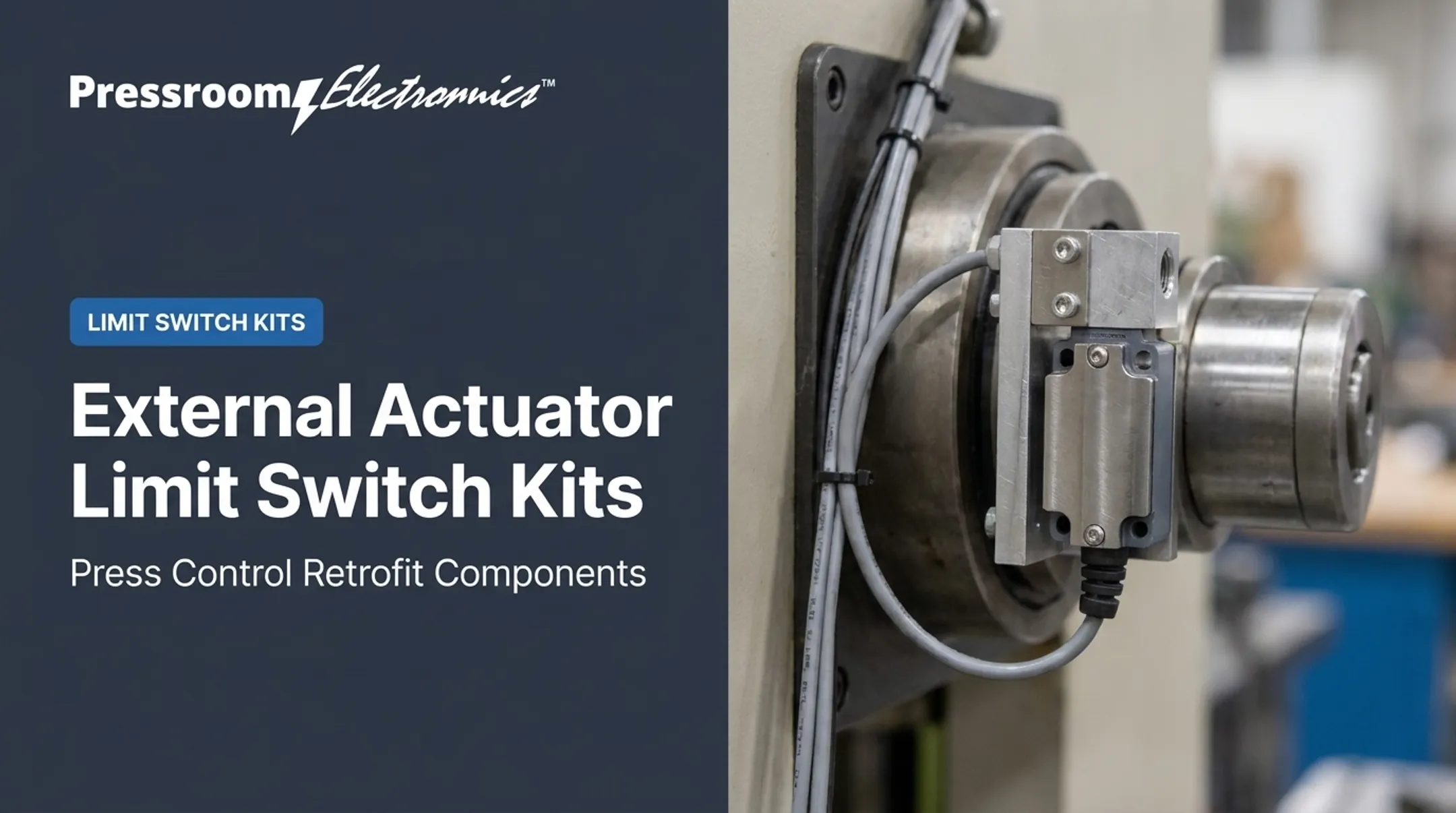
The common problems are overtravel, false triggering, contact wear, misalignment, harsh environments, and confusion over whether a switch belongs in a control or safety function. A rugged housing solves none of these by itself.
This guide covers operating principles, actuator types, contact testing, selection, alternatives, and industrial applications, with pressroom examples throughout.
Key Takeaways
- "Heavy duty" is not a spec; match travel, load, enclosure, and control logic to the application.
- Pick roller, plunger, flexible-rod, or rotary actuators by approach direction and available travel.
- Verify model-level datasheets and safety requirements before using any switch for overtravel or guarding.
- Continuity checks confirm contact state only, not timing or safe operation.
What Are Heavy-Duty Mechanical Limit Switches and How Do They Work?
How a heavy-duty mechanical limit switch works
The sequence is short. A machine target contacts the actuator, the actuator moves the internal mechanism, the contacts change state, and a signal goes to a PLC, relay, contactor, alarm, or controller.
Omron's technical guide describes an enclosed switch that protects its mechanism from external force, water, oil, gas, and dust.
The switch only reports position. The control system decides what happens next: stop, reverse, change sequence, or light an indicator. Contacts are for control circuits, not motor power. Rockwell's direct-opening 802T instructions prohibit direct motor control.
Main construction and heavy-duty features
A typical switch has these parts:
- Actuator that meets the target
- Spring or return mechanism
- Internal contacts and terminals
- Housing, seals, and cable entry
- Mounting hardware
What separates heavy-duty from light-duty is resistance to impact, vibration, repeated actuation, contamination, and temperature swings. Check each claim against the manufacturer's documentation.
As one benchmark, Honeywell's HDLS sheet lists up to 50 million mechanical actuations, 10 g vibration, and 50 g shock (with the actuator not fitted). Those are HDLS figures, not universal numbers, and mechanical life is not electrical life.

Contact arrangements and continuity
In practical control terms:
- COM is the common terminal.
- NO is open at rest and closes when actuated.
- NC is closed at rest and opens when actuated.
Not every switch has one COM/NO/NC group. Rockwell's four-circuit 802T has separate 2 NC + 2 NO circuits. Read the wiring diagram first.
Isolate and de-energize the circuit before putting a meter on it. Continuity depends on which terminals you test and where the actuator sits. It will not prove correct timing, safe operation, or adequate contact performance.
What "high limit" means in mechanical applications
A mechanical high limit detects an upper travel boundary or prevents overtravel. A thermal high limit responds to excess temperature, such as a grain-dryer plenum shutting down on heat. Different devices, different jobs.
Upper-travel switches show up on presses, lifts, hoists, slides, and actuators. OSHA's crane rules, for instance, require a hoisting-direction overtravel limit, and the upper-travel limit must not serve as the operating control. The switch still needs proper stopping logic behind it.
Heavy-Duty Mechanical Limit Switch Types and Applications
Plunger and roller-plunger switches
Direct plungers suit linear movement. Roller plungers cut sliding friction and handle a passing cam or dog. Both need aligned motion, because side loading bends or breaks the shaft. Omron specifically warns about oblique roller or dog engagement.
Typical uses include:
- Machine slides and fixtures
- Press mechanisms and doors
- Transfer equipment and end-of-travel detection
Roller-lever and adjustable-lever switches
A roller lever detects parts moving across the actuator. Roller type, lever length, and approach direction all affect wear and repeatability. Good fits include:
- Conveyors and packaging equipment
- Material transfer lines
- Guarding positions
Avoid hard impacts and approach paths beyond the actuator's permitted travel. Rockwell's direct-opening safety models prohibit adjustable levers in safety applications.
Flexible-rod or whisker switches
Wire-rod and coil-spring actuators catch irregular or lightweight targets from several directions. They help where precise alignment is hard. Omron permits coil-spring actuation from any direction except axial.
Watch for:
- Unintended triggering
- Bending fatigue
- Target speed beyond the actuator's mechanical limits
Confirm those limits before committing.
Rotary and cam-operated limit switches
Rotary switches track shaft rotation or cam position instead of direct linear contact. Geared designs, such as Hubbell's Series 55, use a rotating shaft with adjustable cams operating contact blocks. They suit:
- Hoists, cranes, and winches
- Rotary tables and valve mechanisms
- Machine axes
Rotational range, switching sequence, and mechanical indexing matter most here.
Matching switch types to pressroom applications
In stamping and forming, mechanical switches can confirm ram or slide position, door status, transfer movement, or end of travel. They do not replace a complete press safety system. OSHA 1910.217 separately addresses control reliability, brake monitoring, and die-work protections.
Rotary cam switches are common on mechanical presses. Pressroom Electronics' No. 310A is a NEMA 12 rotary cam switch with drive check, available with 4, 6, or 8 cams. Its spring-loaded mounting absorbs shock and stops the press if the drive chain breaks. Press operators, rebuilders, and OEMs who also need integrated controls, guarding, brake monitoring, or die protection can consult Pressroom Electronics for application-specific guidance on those systems.
How to Select a Heavy-Duty Mechanical Limit Switch
Define the machine movement and target interaction
Document how the target meets the actuator: pushing, sliding across, rotating against, or lightly touching. Record:
- Approach direction
- Speed and force
- Travel distance
- Available overtravel
Operate the actuator within its rated travel and force. Never use the switch as a mechanical stop. Excess overtravel causes malfunction.
Evaluate mechanical duty
Consider cycle rate, impact, vibration, shock, return force, and repeatability. Compare manufacturer ratings for:
- Actuator life
- Pretravel and overtravel
- Operating position
- Differential travel
- Allowable side load
Values are model-specific. Honeywell's LST1H conveyor switch, for example, lists 0.085 N m maximum operating torque and 60 degrees minimum overtravel, which suits light objects but is not a general rule.
Match the electrical configuration and load
Choose NO, NC, or changeover contacts based on control logic and the failure state you want to see. Verify voltage, current, AC/DC rating, inrush, inductive capacity, and terminals.
The load matters. Omron's WL standard-load version has a minimum applicable load of 5 VDC, 160 mA, while its microload version suits 5-30 VDC, 0.5-100 mA for PLC inputs. Contactor coils fall under AC-15 or DC-13 duty, which stresses contacts more than steady current suggests.

Select enclosure and environmental protection
List the exposures: dust, metal debris, oil, coolant, moisture, chemicals, temperature, corrosion, and vibration. Confirm the NEMA or IP rating, cable entry, material compatibility, and mounting orientation on the datasheet.
NEMA and IP ratings are not interchangeable, and NEMA's enclosure guide notes IP cannot convert directly to NEMA types. Common NEMA types include:
- Type 12: dust and dripping
- Type 13: oil and coolant
- Type 4X: washdown and corrosion
Confirm mounting, wiring, and service access
Rigid brackets, actuator clearance, cable routing, and terminal access all drive long-term reliability. Before buying, check:
- Mounting dimensions
- Actuator orientation
- Terminal layout
- Replacement compatibility and spare parts
- Access for inspection and adjustment
Review safety and control-system requirements
A standard limit switch should not automatically serve as an e-stop, guard-locking, or personnel-protection device. Required performance level (ISO 13849-1) or SIL (IEC 62061) follows a risk assessment. Depending on that result, you may need:
- A safety-rated switch
- Positive-opening contacts (IEC 60947-5-1 Annex K)
- Redundancy
- A monitored safety relay or safety controller
For U.S. mechanical power presses, start with OSHA 1910.217 and ANSI B11.1. Involve a qualified machine-safety professional.
Installation, Continuity Testing, and Maintenance
Installation and alignment practices
Apply lockout/tagout before installing, adjusting, wiring, inspecting, or replacing a switch. Then:
- Mount rigidly using the provided holes and hardware.
- Set the correct approach direction.
- Leave actuator clearance and protect it from direct machine impact.
- Orient conduit so fluid cannot drain into the housing.
- Run slow-motion tests to verify switching point, return action, overtravel, and machine response.
On a press, cam timing determines reliable switching. In Pressroom Electronics' Standard #130 setup, suggested starting points are LS1 open at 330-340 degrees and LS2 closed at 310-020 degrees, with LS2 actuating on the upstroke before LS1. LS3 and LS4 vary by job.

Continuity and functional testing
- Identify terminals from the wiring diagram.
- De-energize and isolate the circuit.
- Check the resting state: NC should conduct, NO should not.
- Actuate manually.
- Confirm the states reverse as specified.
Intermittent continuity, failure to return, delayed switching, or odd behavior points to contamination, contact wear, wiring faults, binding, or the wrong configuration.
Troubleshooting and preventive maintenance
Common failure causes:
- Loose mounting or misalignment
- Damaged rollers or plungers
- Broken conductors
- Moisture ingress and debris buildup
- Vibration and excessive impact
- Contact arcing, welding, or electrical overload
Build these checks into your preventive maintenance routine:
- Inspect mounting, terminals, and actuators on a set schedule
- Clean per the manufacturer's instructions
- Inspect before use after three months or more in storage (Omron guidance)
- Keep oil and grease off actuator moving parts
- Replace damaged devices
- Never bypass a switch without evaluating control and safety consequences
On presses, switch faults often lock out the control. LS1L, LS2L, and LS3L faults can mean a broken switch or open wiring, while LS1H and LS2H can mean shorted wiring.
Mechanical Limit Switches vs. Alternatives
Common alternatives
| Alternative | Best for | Watch for |
|---|---|---|
| Inductive | Metal targets | Range varies by target and model |
| Capacitive | Solids, liquids, nonmetals | Humidity, dielectric constant |
| Photoelectric | Non-contact detection | Dust, reflectivity, ambient light |
| Magnetic/reed | Magnet-equipped targets | Model-specific range |
| Encoder | Shaft or angular position | Interface compatibility |
| Safety interlock | Guard position | ISO 14119 selection |
Non-contact options remove actuator wear but add requirements:
- Power supply and electronic outputs
- Target characteristics and sensing distance
- Alignment, contamination, and interference
Pressroom Electronics' PressCam 8 is a programmable alternative. It uses an absolute-positioning transducer instead of physical limit switches and can be programmed to act like them.
When mechanical contact remains advantageous
Contact still makes sense for:
- A defined end-of-travel point
- Targets that are hard to sense electronically
- Retrofits on aging machinery
- Circuits that need dry contacts
Relay outputs, for example, provide dry NO or NC contacts at voltages up to half the relay rating. Tradeoffs include wear, actuator damage, contact bounce, contamination, and alignment.
A practical decision framework
Ask:
- Is contact acceptable?
- How fast and how often does the machine cycle?
- What is the target made of?
- How harsh is the environment?
- What output does the controller require?
- Is the function safety-related?
Compare answers against current datasheets. For press or guarding upgrades, bring in a qualified controls or machine-safety professional.
Frequently Asked Questions
How does a mechanical limit switch work?
Physical contact moves an actuator, which changes the state of internal electrical contacts. That change signals the machine control system.
Are mechanical limit switches supposed to have continuity?
It depends on the terminal pair and actuator position. A closed pair conducts and an open pair does not. Test only on an isolated circuit, using the manufacturer's wiring diagram.
What are the main types of mechanical limit switches?
Plunger, roller-plunger, roller-lever, adjustable-lever, flexible-rod (whisker), and rotary or cam-operated. The right one depends on how the machine moves.
What is a high limit switch?
A mechanical high limit detects upper travel or overtravel. A thermal high limit protects against excess temperature. Specify which one you mean.
What are some alternatives to mechanical limit switches?
Inductive, capacitive, photoelectric, magnetic, encoder-based, and safety-interlock devices. Each has its own installation and control requirements.