The vocabulary gets messy fast. Sensor, transducer, detector, switch, encoder and resolver overlap in catalogs and conversation. This guide defines each term in plain shop-floor language, walks through five common devices, and covers applications, selection and limitations, with a focus on press and automation systems.
Key Takeaways
- An electromechanical sensor turns mechanical movement, deformation or contact into an electrical signal.
- Limit switches, potentiometers, encoders, resolvers and LVDTs sense. Motors, relays and solenoids mostly act.
- Contact versus non-contact, and on/off versus proportional output, drive most selection decisions.
- Match the sensor to the variable, output, environment, mounting and controller.
What Are Electromechanical Sensors and How Do They Work?
How an electromechanical sensing device operates
An electromechanical sensing device detects a physical input through a mechanical element, an electrical interaction, or both. It then produces a signal for a controller, display or monitoring system.
The signal path usually runs in three steps:
- A physical condition (movement, pressure, strain, rotation or contact) changes.
- A transduction method converts that change into an electrical output.
- Signal-conditioning electronics make the output usable by a controller.
Common transduction principles in industrial sensors:
- Variable resistance: a potentiometer wiper slides along a resistive element.
- Inductive coupling: an LVDT core changes coupling between primary and secondary coils.
- Magnetic switching: float magnets close reed switches in tanks and pump skids.
- Capacitance: displacement changes capacitance between sensor and target.
- Strain-based measurement: force deforms a gauge, changing resistance and bridge voltage.
Sensor, transducer, detector, switch
The International Electrotechnical Commission (IEC) vocabulary separates these terms:
- Sensor: the element directly affected by the measured quantity that generates a related signal
- Transducer: transforms energy between two forms
- Detector: discerns the existence or variation of signals
- Mechanical switch: makes, carries and breaks current
In practice, a sensor measures, a detector flags a condition, and a switch reports a discrete state. Honeywell calls a limit switch an electromechanical digital position-sensing device, so the categories overlap.
Contact versus non-contact
Contact devices give direct mechanical confirmation but can wear. Non-contact devices, such as free-core LVDTs and magnetic encoders, avoid that wear. They need careful spacing, alignment and target selection instead.
Types and Examples of Electromechanical Sensors
Five familiar examples
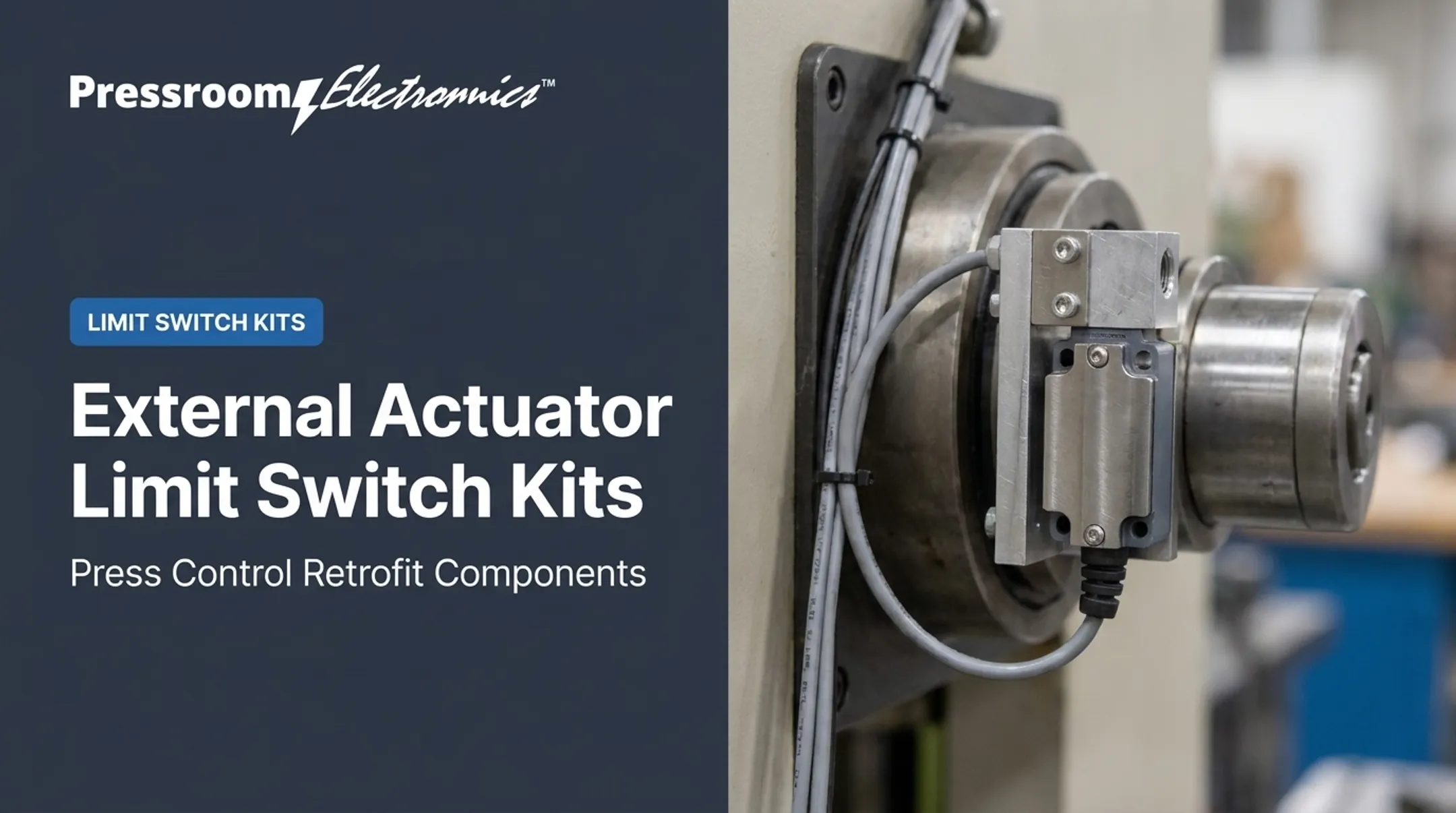
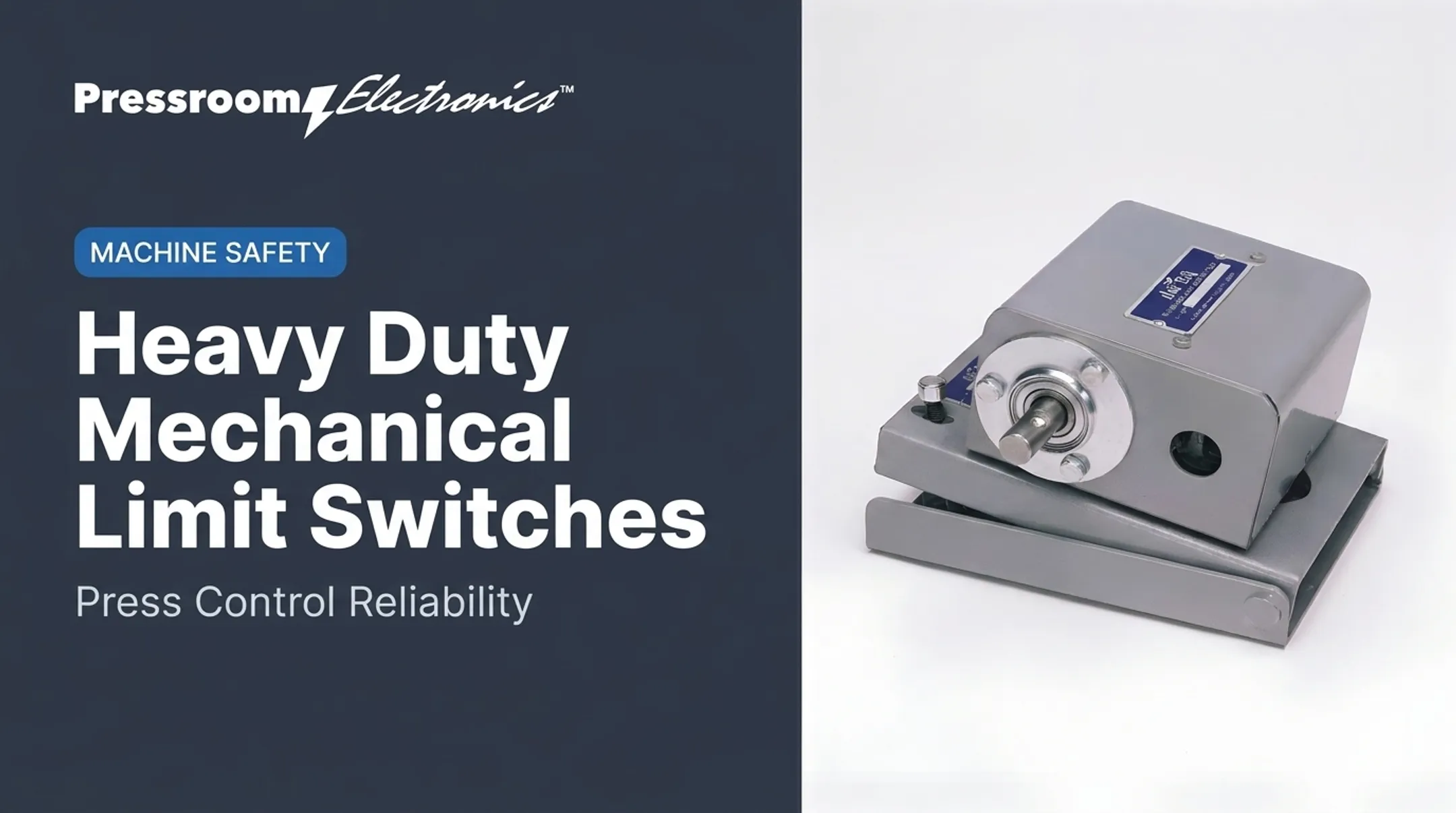
Limit switch. Actuator travel changes normally open or normally closed contacts, giving a discrete position signal. Actuator and stroke must match the application, and Omron's precautions warn that excessive travel can damage it. Durability depends on switching conditions.
Potentiometer. A wiper moves along a resistive strip and the output tracks rotary or linear position. It is simple and works well for joint feedback in robotics. Input loading can affect linearity and life, and the wiper wears.
Rotary encoder. Shaft rotation becomes pulses or coded position. Incremental output reports movement and needs counting or reference recovery after power loss. Absolute output supplies a position word that is correct when power returns.
Resolver. An AC rotary transformer outputs sine and cosine signals representing shaft angle. With no onboard electronics, it tolerates harsh conditions. Digital controls need a conversion step.
LVDT. A moving core changes differential secondary voltage, and phase shows direction from null. Free-core versions have no sliding contact. Resolution is limited by the electronics, not the coil.

How sensor types differ by measurement and output
Sensors can be grouped by what they measure: position, angle, speed, presence, force or machine state. Two sensors measuring the same variable can use different principles. A resolver and an incremental encoder both report crank angle, but one gives an analog transformer signal and the other gives pulses.
Outputs fall into two families. Discrete outputs come from a switch changing state. Proportional or coded outputs include analog position, pulse trains, resolver signals and digital position words.
Motors, relays, solenoids and actuators are electromechanical devices, but they mainly create movement or switch power. Sensors provide information.
MEMS devices use microscopic mechanical structures made with semiconductor-style fabrication. Analog Devices describes MEMS accelerometers for detecting bearing, cavitation and gear-mesh faults. Most press-room sensors are larger parts built for easy installation and service.
Industrial Applications of Electromechanical Sensors
Manufacturing and machine automation
Position, speed, presence and force feedback tell automated equipment whether a cycle is running correctly and whether a part is where it should be.
On punch presses, typical sensing points include:
- Crankshaft position
- Clutch and brake timing
- Slide position and shut height
- Die protection (feed, part ejection, buckling, stripper position)
- Guarding interlocks
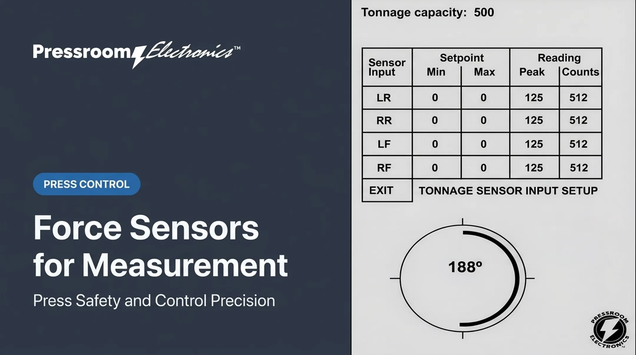
- Tonnage
Wintriss documents a resolver driven 1:1 with the crankshaft, with product-specific timing accuracy stated within 2/3 degree.
Pressroom Electronics builds resolver-based and rotary-cam-based clutch/brake controls. Its brushless resolver replaces a mechanical rotary cam switch and provides absolute shaft-position feedback. It supports cable runs up to 600 feet and a 3/4-inch shaft.
The PressCommander adds a self-checking resolver input each cycle and a built-in motion detector. Its LT-1900 stopping-time monitor uses a linear encoder to detect press position and speed.
A feedback loop looks like this: the sensor detects a condition, the control interprets it, and the system permits a cycle, stops the press, sounds an alarm, logs a reason code or prompts maintenance. Pressroom's PDMS supports up to 20 customizable downtime codes.

Safety functions need care. OSHA 1910.217 requires, for example, that an interlocked barrier guard interlock with clutch control, and that brake monitoring prevent another stroke where required.
Programmable cams on the SmartPAC PRO are expressly prohibited for clutch/brake safety timing. Always validate safety functions against current OSHA, ANSI and manufacturer documents.
Other industrial environments
- Conveyors and packaging: Avtron replaced an encoder damaged by shaft runout with a magnetically coupled design and reported less encoder downtime.
- Machine tools: encoders gauge backstop position and direction.
- Robotics: potentiometers give joint feedback.
- Stamping and press rebuilding: resolvers, strain-based tonnage monitors and die sensors.
Environment shapes the choice. Shock, vibration, lubricant, metal debris, temperature, electromagnetic interference, cycle rate and tight access all matter. Pressroom's PressCam 8 resolver transducer, for instance, is rated for 200 G shock for 11 milliseconds, −20°C to 125°C, and a NEMA 13 enclosure.
How to Select and Integrate an Electromechanical Sensor
Start with the measurement requirement:
- Variable and range
- Resolution and repeatability
- Response time and acceptable error
- Discrete state or continuous feedback
Resolution and range still have mechanical limits. Dynapar notes that more increments do not fix mechanical error, and LVDT linearity falls off outside its specified range.
Next, match the interface to the machine:
- Mounting method, shaft or travel geometry, alignment and actuation force
- Supply voltage, output type and controller compatibility
- Shielding, connectors and cable routing
- Ingress rating (some limit switches are IP67, though Omron separately cautions about oil, debris and vibration)
Mounting clearance and cable routing decide whether those interface choices hold up on the floor. The LT-1900 linear sensor, for example, needs other metal kept 0.5 inch from its housing and its magnet held about 0.1 inch above the sensor. Keep its encoder cable out of any conduit hole shared with high-voltage lines. Resolver cables likewise need separation from high-current lines to prevent nuisance faults.
Then commission and maintain:
- Verify installation and set the reference position (for example, top dead center).
- Test signals during real machine cycles.
- Check the whole safety system at the start of every shift.
- Inspect for wear, misalignment and wiring damage.
- Confirm replacement parts remain available.
Benefits, Limitations, and the Relationship to MEMS
Benefits
- Direct machine feedback
- Deterministic switching or position signals
- Straightforward troubleshooting
- Compatibility with established controls
- Suitability for rugged environments when properly specified
Limitations
- Wear and bounce: Omron documents contact chatter, welding and damage tied to switching conditions.
- Backlash and drift: gearbox play is invisible to the encoder, and temperature and lead-wire errors affect strain measurement.
- Noise: electronics limit LVDT resolution, and encoder transmission picks up noise. Pressroom's controls filter inputs digitally, yet excessive noise can still shut a press down.
- Contamination, vibration and alignment: all can cause faults. Non-contact sensing removes some problems, not installation or environmental ones.
When to choose conventional over MEMS
Choose a conventional sensor when you need direct crank angle, linear travel or a discrete position at machine scale, with serviceable mounting and an interface your control already accepts. A resolver suits press crank angle, an LVDT suits linear displacement, and a limit switch suits discrete position.
MEMS earns its place in vibration and condition monitoring, where small size and low power count. NIST describes MEMS as integrated devices for sensing and other functions. Conventional and MEMS sensors fill different roles on the machine.

Frequently Asked Questions
What is an electromechanical sensing device?
It detects a physical condition through mechanical movement, deformation, contact or electromagnetic interaction. It converts that condition into an electrical signal.
What are five examples of electromechanical devices?
A motor, relay, solenoid, actuator and switch. Switches sense a condition such as position, while the others mainly create movement or switch power.
How do electromechanical sensors work?
A physical input causes a mechanical response or interaction. Transduction makes an electrical signal, conditioning cleans it up, and the controller interprets it.
What is the difference between a sensor and a switch?
A sensor can give continuous, proportional or coded measurements. A switch usually reports a discrete state such as on/off or reached/not reached.
How are electromechanical sensors used in manufacturing?
They provide position feedback, part detection, speed monitoring, clutch and brake timing, guarding, die protection and machine status. Controls use those signals to allow or stop cycles.