"Travel safety trip control" gets used loosely. People mix it up with emergency stops, shunt-trip breakers, and ordinary limit switches. Choosing the wrong device or control philosophy can leave hazardous motion, stored energy, or restart risk unaddressed.
This article covers how trip logic works, which components are involved, how it applies to mechanical punch presses, and how to specify, validate, and maintain the system.
Key Takeaways
- A trip control is a full safety function: detection, stop, feedback, reset, and restart prevention.
- Energize-to-trip or de-energize-to-trip should follow the risk assessment, not habit.
- Presses may need coordinated clutch/brake controls, guarding, die protection, and brake monitoring.
- Testing and maintenance must follow manufacturer instructions, lockout/tagout, and OSHA and ANSI requirements.
What Are Travel Safety Trip Controls?
No public standard defines travel safety trip control as a term. Standards speak of safety functions, safety-related control functions, and emergency-stop functions.
In this article, the term means a control function that detects a hazardous condition and commands a safe stop, or inhibits hazardous travel of the press slide or ram.
How It Differs from Related Devices
Each device addresses a different hazard and commands a different action:
| Device | What it addresses | Typical action |
|---|---|---|
| Emergency stop | Human response to an actual or impending emergency | Stops the machine; complementary protection only |
| Light curtain | Operator intrusion during the downstroke | Stops or prevents slide motion |
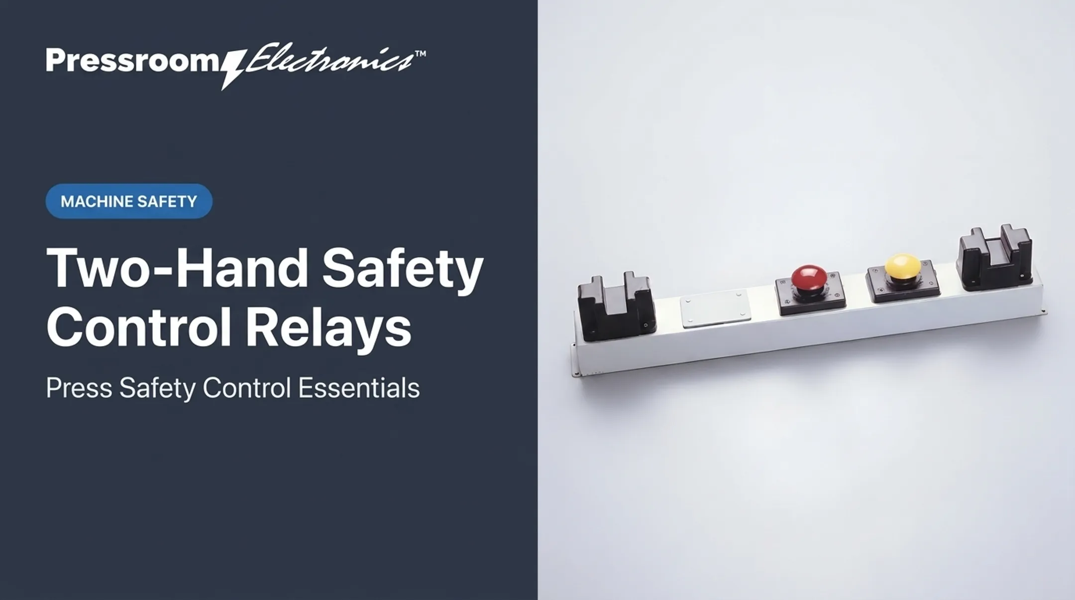
| Two-hand control | Hands in the die area | Slide stops if either control is released |
| Overtravel or limit switch | Slide past a set position | Signals a stop or lockout |
| Safety relay | Evaluates inputs and faults | Drives outputs, monitors contacts |
| Clutch/brake control | Executes the stop | Releases clutch, applies brake |
| Shunt-trip breaker | Remote electrical interruption | Opens a breaker; not qualified press safeguarding |
Presence-sensing devices cannot be used on full-revolution clutch presses, because that type of press completes its cycle once engaged. Part-revolution clutches can disengage during the downstroke.
Safe State and Limits
For a part-revolution press, the safe state is clutch released and brake applied when the engaging means is removed, deactivated, or de-energized. That is not energy isolation.
Stopping travel does not remove stored electrical, pneumatic, hydraulic, or mechanical energy. Pushbuttons and selector switches are not energy-isolating devices, and a trip control never replaces lockout/tagout under OSHA 1910.147.
How Trip Logic Moves Equipment to a Safe State
De-Energize-to-Trip vs. Energize-to-Trip
In a de-energize-to-trip design, loss of power or a detected fault drives outputs to zero. OSHA's press rules line up with this: part-revolution clutches must release and brakes apply when the engaging means is deactivated or de-energized.
Energize-to-trip designs need more care. Functional-safety analysis, as Analog Devices notes, must include the power supply, because a supply failure could then leave the system unable to trip. Backup power and supply monitoring become part of the safety function.
Neither approach is universally correct. The required press safe state and the risk assessment decide.
The Safety Chain
A representative sequence runs like this:
- An initiating device (light curtain, guard interlock, e-stop) detects a condition.
- A safety relay or safety PLC evaluates inputs and checks for faults.
- The final control element, usually a monitored dual clutch/brake valve, exhausts air.
- The clutch releases and the brake applies.
- Feedback contacts and a brake monitor confirm the press responded.
Stopping performance, brake condition, slide position, and residual motion must be evaluated together. A brake that stops the slide late can defeat a light curtain mounted at the right distance on paper.

Single-Channel vs. Monitored Architectures
Single-channel designs can lose the safety function on one fault. Control-reliable systems are typically dual-channel with monitoring.
Under OSHA 1910.217(c)(5), where it applies, a control failure must not prevent normal stopping. It must also block the next stroke until corrected, and the failure must be detectable or indicated. Performance level (a through e) comes from the risk assessment.
Reset and Restart
- The initiating hazard must clear before reset.
- Reset should be deliberate. An e-stop reset must not restart machinery automatically.
- Restoring air or power alone is not enough after a clutch-engaging power or pressure failure.
- Reset must not itself cause hazardous motion. Verify this during commissioning.
Components and Pressroom Applications
Initiating Devices
- Emergency-stop devices
- Interlocked guards that prevent clutch activation unless guards are in position
- Light curtains
- Two-hand controls and two-hand trips
- Travel or overtravel sensing
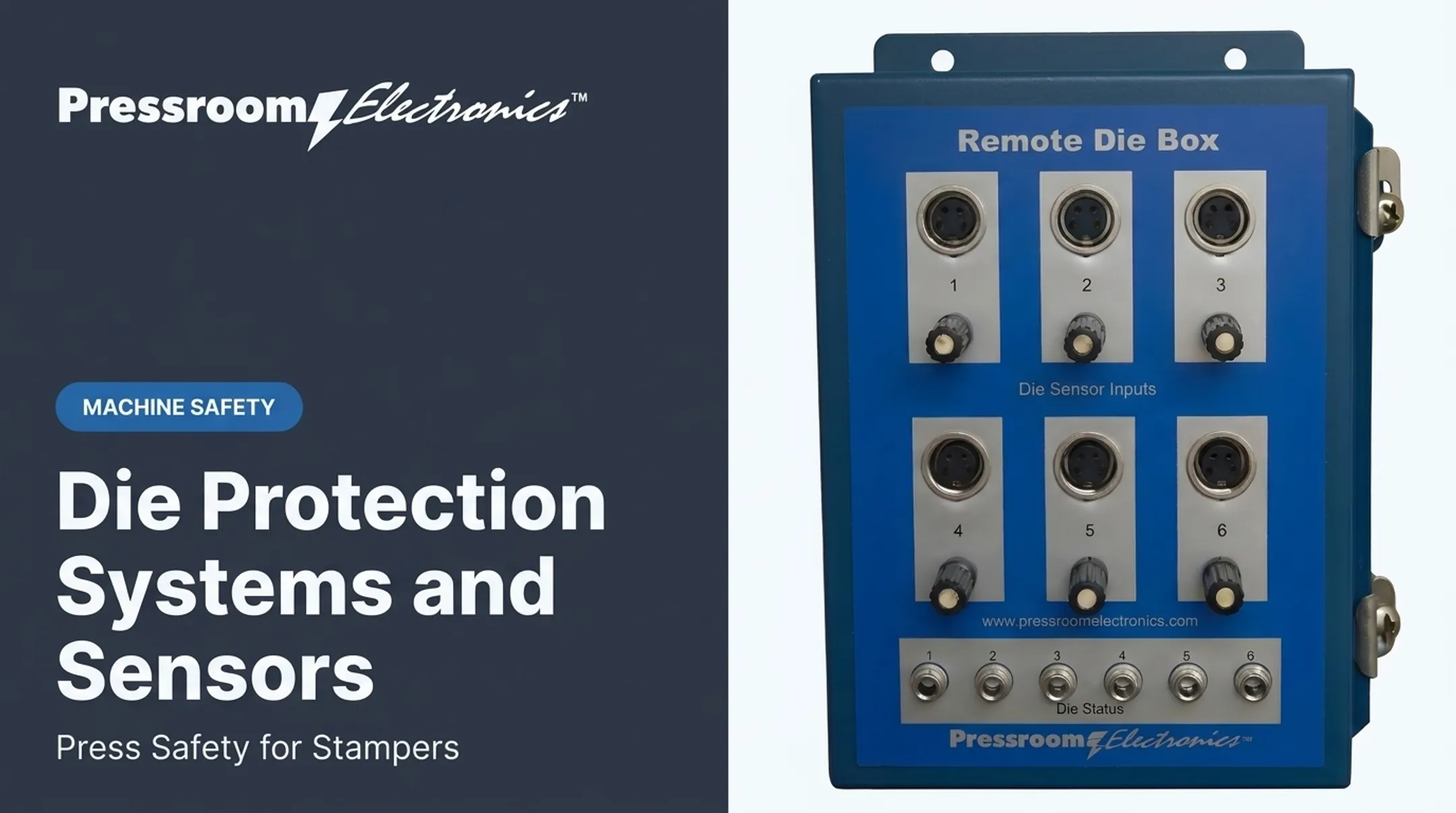
- Die-protection and misfeed signals
- Brake or position faults
Logic, Final Control, and Feedback
Safety relays and safety PLCs evaluate inputs, detect faults, and control outputs. They can report a trip reason, but diagnostic convenience must never weaken the safety function. Cross-checking and force-guided contacts help catch welded contacts.
On the output side:
- Monitored double valves exhaust the clutch/brake circuit on a valve fault
- Brake monitors supervise stopping performance, though a brake monitor is not itself safeguarding
- Status contacts and position feedback confirm the press responded
Example: A Part-Revolution Punch Press
This is one example only. Architectures differ by press.
A resolver-based control on a part-revolution air-clutch press might coordinate:
- Palm buttons or a light curtain at the point of operation
- Interlocked guards
- Die-protection inputs that signal a top stop on a misfeed
- A programmable limit for slide position
- A brake monitor that blocks the next stroke if stopping time exceeds its threshold
- A restart permissive requiring a keyswitch or deliberate reset
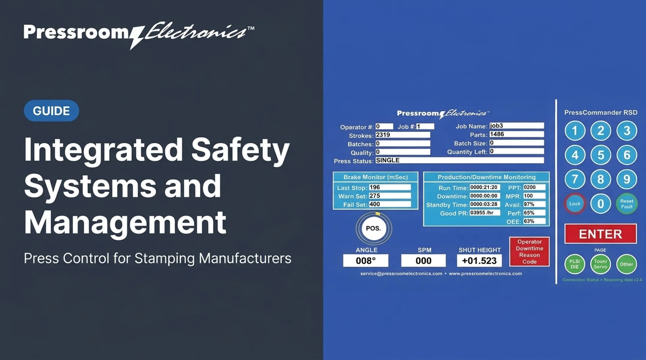
Pressroom Electronics manufactures resolver-based and rotary-cam clutch/brake controls, brake monitors, die protection, and guarding for stampers, rebuilders, and OEMs. If you're upgrading any of those functions, confirm model-specific compatibility and application requirements before you buy. These controls are for part-revolution presses and are not for full-revolution machines.
Safety Distance Depends on Measured Stopping Time
OSHA's baseline for presence sensing is a distance greater than Ds = 63 in/s × Ts, with stopping time measured near the 90-degree crank position. OSHA's eTool adds control response, sensor response, brake-monitor allowance, and penetration depth. Use measured values, and recalculate after changing a brake-monitor timer or stop-position sensor.

Designing, Installing, Testing, and Maintaining the System
Start with the Risk Assessment
Before choosing parts, document:
- Hazardous travel and stopping distance
- Residual energy and access points
- Foreseeable misuse
- Required performance level
- Applicable standards, including OSHA 1910.217, ANSI B11.1, B11.19, B11.26, and NFPA 79
ISO 12100 gives the risk assessment framework, and ISO 13849-2 covers validation.
Specification Checklist
- Press type, age, and clutch/brake arrangement
- Control voltage and environmental conditions
- Input and output devices
- Response time
- Diagnostic needs
- Retrofit constraints and fit with existing panels
Installation
Qualified personnel should install the system per the manufacturer's schematics, under lockout/tagout.
Follow sound wiring and documentation practice:
- Correct conductor and terminal methods
- Shielded cable where specified
- Separation of power and control wiring
- Clear labels and documented change control
Never bypass, defeat, or force a trip device. OSHA requires that clutch actuation be prevented when all operating stations are bypassed.
Commissioning and Validation
Test:
- Every initiating device and its trip response
- Fault or power-loss response where permitted
- Clutch and brake action
- Status feedback
- Reset sequence and restart prevention
- Actual stopping time under controlled conditions
Record the machine, test condition, result, corrective action, responsible person, and approval status.
Ongoing Reliability
There is no universal proof-test interval. OSHA's 1910.217 requirements call for periodic inspections with dated, signed records including the press serial number.
Directed inspections of clutch/brake, anti-repeat, and single-stroke mechanisms occur at least weekly, though presses meeting both (b)(13) and (b)(14) are excluded. Manufacturers often add shift-start checks.

Between formal inspections:
- Review trip and reason-code history
- Investigate nuisance trips instead of suppressing them
- Inspect brake and sensing components
- Repeat validation after changes to controls, software, tooling, or sequence
Hazards outside sensing coverage still matter. A 2016 New York FACE investigation found a worker killed by an ejected safety block that was not interlocked, outside the light-curtain perimeter.
Conclusion: Make the Trip Function Verifiable
An effective travel safety trip control is an engineered chain linking hazard detection, logic, stopping hardware, feedback, reset, and maintenance. Treat it as that full chain, not as a switch or breaker accessory.
Next steps:
- Document the press hazard and safe state
- Confirm compatibility with the existing clutch/brake and guarding architecture
- Have a qualified professional validate the finished system before production use
Frequently Asked Questions
What are travel safety trip controls?
They are controls that detect a hazardous travel or machine condition and command a safe stop or inhibit movement. The exact architecture depends on the machine and risk assessment.
How are travel safety trip controls different from an emergency stop?
An emergency stop is one possible initiating device. The trip-control function also includes logic, the final stopping mechanism, feedback, reset, and restart controls.
Should a safety trip control be energize-to-trip or de-energize-to-trip?
It depends on the required safe state, hazard analysis, failure response, and performance requirements. Have a qualified engineer review the choice.
Can a shunt trip breaker stop a mechanical punch press?
A shunt trip interrupts electrical power but isn't qualified press safeguarding. It may not address clutch/brake response, stored energy, stopping distance, or restart prevention.
What components are typically used in a press safety trip circuit?
Typical parts are initiating devices, safety relays or PLCs, clutch/brake valves, brake monitoring, and feedback contacts. Guarding, die protection, and reset controls are added as the press requires.
How should travel safety trip controls be tested and maintained?
Document commissioning tests, then run periodic functional tests and inspections per OSHA and the manufacturer. Investigate faults, use lockout/tagout when servicing, and revalidate after any modification.