The hard part is the selection. A poorly chosen guard and interlock create nuisance stoppages, invite bypassing, or leave workers exposed during setup, jam clearing, and maintenance. A German DGUV/IFA survey of 839 professionals found that 45.4% of respondents reported movable guards defeated frequently or permanently. That isn't a U.S. prevalence figure, but it shows how common defeat is.
This article covers interlocks versus guard locking, device types, selection and design, press applications, and inspection practices.
Key Takeaways
- An interlock stops hazardous operation when a guard opens, but it doesn't replace lockout/tagout.
- Guard locking is needed when motion, heat, or stored energy persists after a stop command.
- Select devices by risk, stopping time, environment, access frequency, and foreseeable defeat.
- Validation, testing, and maintenance matter as much as the device rating.
What Interlocking Machine Guards Do
What is an interlocking machine guard?
An interlocking machine guard is a movable guard paired with an interlocking device and the machine control system. Three behaviors define it:
- Hazardous motion can't start while the guard is open.
- Opening the guard commands the appropriate stop.
- Closing the guard doesn't restart the machine on its own.
A fixed guard normally needs tools to remove. A movable guard (hinged door, sliding gate, removable panel, access hatch) doesn't, so it needs position monitoring wherever workers can reach a hazard through it.
How does an interlock work?
The signal runs from the guard's actuator or sensor to a safety relay or safety controller, then to the final control elements such as a clutch/brake or motor contactors. The complete safety function, not the switch alone, must deliver the required risk reduction.
Stopping performance matters too. The design must account for control response time, machine stopping time, opening size, and any motion or stored energy that continues after the stop command.
Interlocking versus guard locking
An interlock monitors the guard and initiates or prevents operation. Guard locking physically holds the guard closed until a safe condition is confirmed.
A conveyor that stops promptly may need only an interlock. A punch press, flywheel, rotating tool, or robotic cell with rundown or stored energy may need locking. The documented risk assessment makes the call.
Pilz's guidance says personnel-protection locking applies when access time is shorter than stopping time.
Interlocks are not energy isolation
An interlock is an engineering safeguard for defined access conditions. Under OSHA 1910.147, control-circuit devices are not energy-isolating devices. Lockout/tagout isolates hazardous energy before servicing, cleaning, or die work.
Warning: Never bypass, defeat, or rely on an interlock during maintenance. Follow OSHA requirements and your site's procedures.
Types of Interlocking Machine Guards and Devices
Common types of machine guards
OSHA's 3170 guide distinguishes these types:
- Fixed: permanently encloses the hazard area. No interlock needed.
- Movable: access doors and gates. These typically need interlocking.
- Adjustable: adjusted for different production operations. Adjustability is not an interlocking function.
- Self-adjusting: moves with the size of stock entering the point of operation.
- Presence-sensing: light curtains and mats, which use other protective methods.
Construction (solid panel, mesh, door, sliding barrier) must prevent reach-through, and it must be coordinated with the interlock's trip point.
Interlock device types under ISO 14119
ISO 14119:2024 groups devices by principle and coding:
| Type | Principle | Typical example |
|---|---|---|
| 1 | Mechanical, uncoded | Cam- or hinge-operated position switch |
| 2 | Mechanical, coded | Tongue-operated safety switch |
| 3 | Non-contact, uncoded | Basic magnetic or inductive sensor |
| 4 | Non-contact, coded | Coded magnetic or RFID device |
| 5 | Trapped-key systems | Added in the 2024 edition |
- Type 1: Sensitive to misalignment and easy to defeat
- Type 2: Actuators must be secured against removal or misuse
- Type 3: Needs attention to environment, alignment, and defeat resistance
- Type 4: Coding resists simple bypass methods when installed properly
Coding level is independent of guard locking.
Mechanical, electrical, and fluid-power interlocks
Mechanical interlocks, electrical switches and sensors, and fluid-power arrangements each fit different machines. Match the technology to the power system, failure modes, environment, and required safety architecture.
Choosing between devices
Compare options against these factors:
- Guard movement and access frequency
- Coding needs and defeat risk
- Contamination, vibration, and washdown exposure
- Misalignment risk and available space
- Residual hazards and whether locking is needed
Before choosing a model, review its safety ratings, wiring requirements, diagnostics, holding force, environmental rating, and installation instructions. Specs vary by model. One EUCHNER locking unit, for example, lists 2,000 N holding force, which isn't a category benchmark.
How to Select and Design an Interlocking Guard System
Start with a machine-specific risk assessment
Identify every hazardous motion and energy source, who can reach it, how access happens in production and maintenance, and which tasks tempt workers to bypass the guard.
Then verify the standards for your machine type and current edition, rather than treating any list as universal. Common references include:
- OSHA 1910.212 and, for mechanical presses, 1910.217
- ANSI B11.0, B11.19, and B11.26
- ISO 12100, ISO 13855, ISO 13857, and ISO 13849-1
Design the complete safety function
Map the chain: guard, actuator, interlock inputs, safety relay or controller, logic, and final switching elements such as clutch/brake or motor contactors.
Redundancy, diagnostics, monitoring, reset behavior, and fault detection must match the required risk reduction. One device can't establish system-level safety.
Don't use ordinary switches or generic sensors in a safety function unless the full design, diagnostics, and architecture support it.
Account for stopping time and safety distance
Measure or obtain the machine's stopping time. Guard location, opening size, hinge movement, and actuator travel all change the effective distance to the hazard. Take distances and opening dimensions from current OSHA, ANSI, and ISO guidance (ISO 13855 and 13857 are the starting points), not from rules of thumb.
If the machine can't stop before someone reaches the hazard, or stored energy persists, add guard locking or another protective measure.
Reduce foreseeable defeat
Use these technical measures:
- Apply appropriate coding
- Use secured actuators
- Install tamper-resistant mounting
- Specify guarded switch bodies
- Place devices so substitution is difficult
The IFA (Institute for Occupational Safety) identifies safeguards that obstruct tasks like troubleshooting, cleaning, or setup as bypass incentives. Give workers legitimate, safe access for those jobs. When a bypass turns up, investigate workflow, downtime pressure, access frequency, and guard design, not only discipline.
Validate and document the installation
Commissioning checks:
- Confirm guard alignment and actuator engagement
- Verify stop behavior and restart prevention
- Check reset location and function
- Test guard-lock release conditions
- Validate response under emergency conditions
- Confirm response to foreseeable single faults
Document the risk assessment, schematics, device specs, validation results, operating instructions, training, and retrofit changes. Any later change to the guard, interlock, control logic, machine speed, tooling, or process should trigger a review of the safety function.

Interlocking Guards in U.S. Press Applications
Press-specific hazards and safeguards
On mechanical punch presses, interlocks appear on access doors, enclosures, and die-space barriers. They're one piece of a broader strategy. Common hazards include:
- Point-of-operation access
- Unexpected cycling and ram movement
- Clutch and brake performance issues
- Die changes and flywheel motion
- Stored pneumatic or hydraulic energy
OSHA 1910.217 sets specifics:
- Interlocked barriers must prevent clutch activation unless the guard position conforms to Table O-10.
- Manual feeding through movable barrier sections is prohibited.
- Type A gates close before the stroke and stay closed until slide motion ceases. Type B gates prevent access before die closure or cessation of downward slide motion.
- Brake performance must be monitored each stroke.
Note that 1910.217 excludes press brakes and hydraulic/pneumatic power presses, though general guarding rules still apply.
Interlocks work alongside fixed barriers, presence-sensing devices, two-hand controls, brake monitoring, emergency stops, and lockout/tagout. None is sufficient alone.
Retrofitting aging presses
A practical sequence:
- Document the existing machine and hazards.
- Assess the current control architecture.
- Identify inadequate or bypassed guards.
- Measure stopping performance. Test at the fastest speed, with the heaviest die, at the 90° downstroke position.
- Select compatible safety devices.
- Integrate the safety circuit.
- Validate the finished system.
Older mechanical presses often need coordinated upgrades to clutch/brake controls, brake monitoring, die protection, and guarding. Otherwise the new interlock works as an isolated component.

Pressroom Electronics
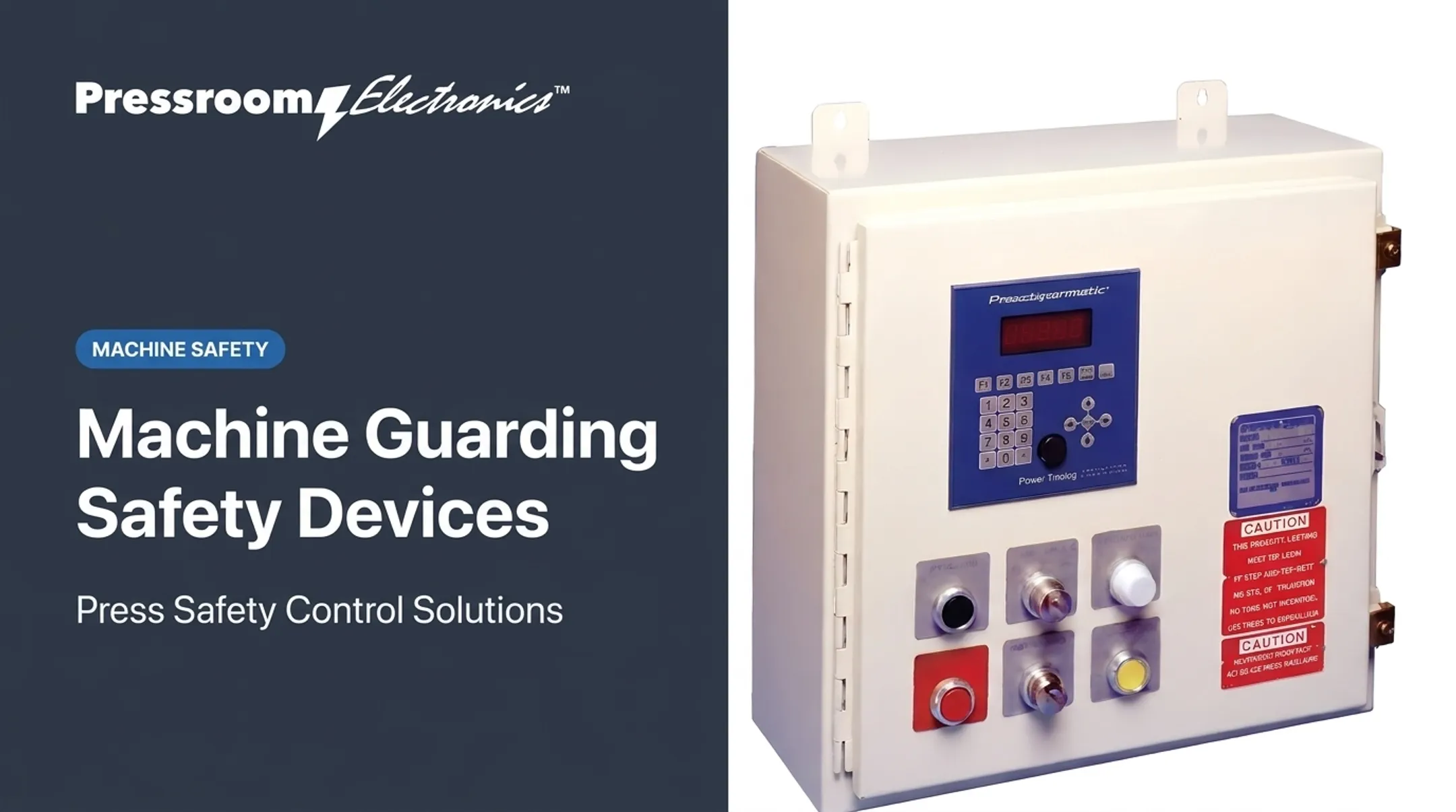
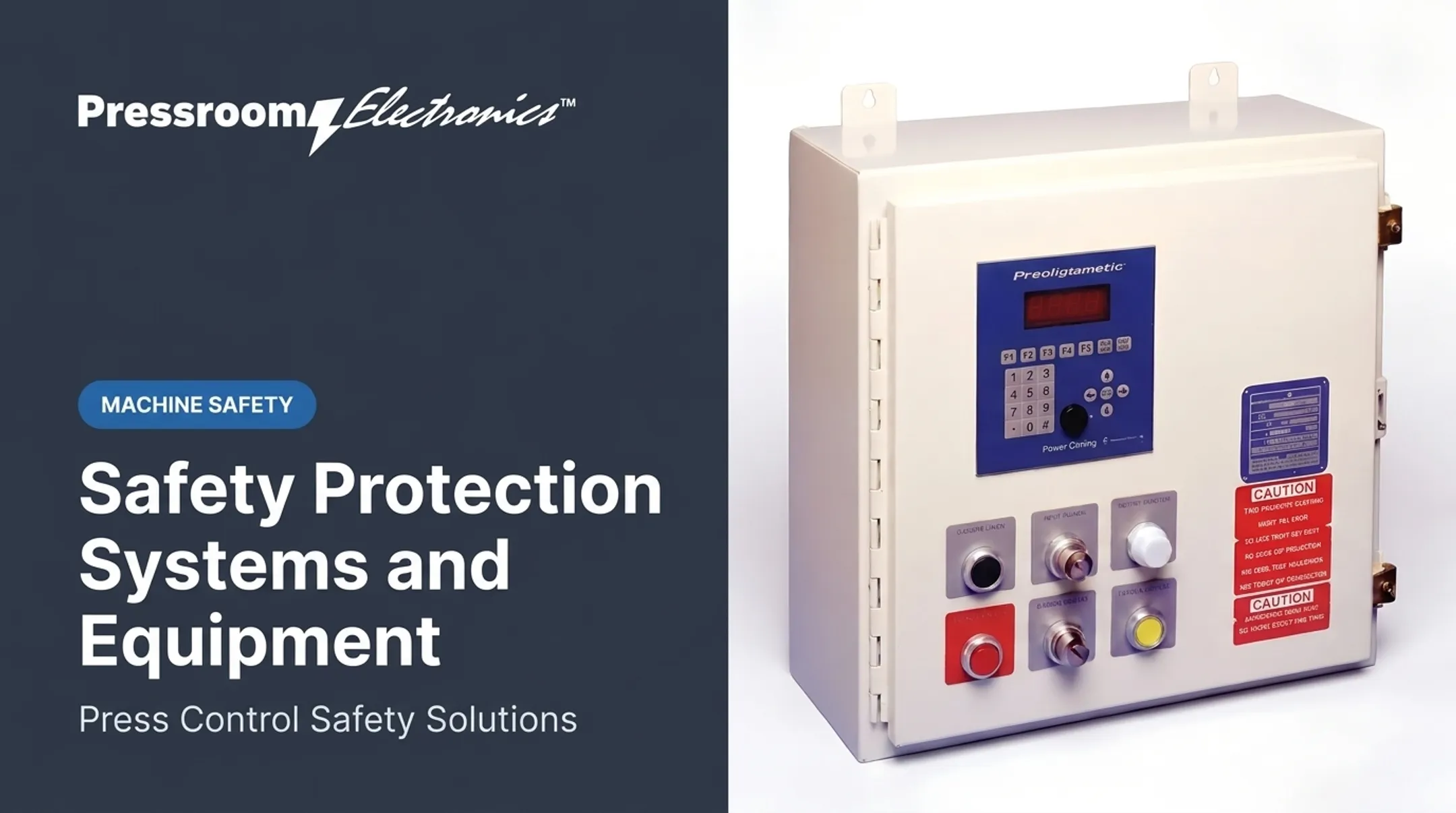
Pressroom Electronics provides press controls and automation for metal stamping and forming equipment, including guarding, brake monitoring, die protection, and customized control applications. Press owners, rebuilders, OEMs, and plant engineering teams can work with them when an interlocked guard must integrate with an existing press control. Buying a control product alone does not establish OSHA or ANSI compliance; the full installation and safeguarding still have to be completed and validated.
Inspection, Testing, and Common Failure Modes
Routine physical inspection
Maintenance staff should check:
- Guard panels, hinges, and latches
- Actuators, switches, cables, and connectors
- Mounting hardware and alignment
- Contamination, damage, and wear
- Signs of tampering or bypass
Watch for these warning signs:
- Guard that sags or takes force to close
- Repeated trips
- Loose actuator
- Defeat with a tool, tape, wire, or spare actuator
Functional testing and records
For each guard:
- Open it during a safe test condition.
- Verify the hazardous function stops.
- Confirm the machine can't restart with the guard open.
- Close the guard.
- Verify a separate, intentional restart is required.
For locking guards, confirm the guard stays secured while the hazard persists and releases only under the validated safe condition.
Set intervals from the risk assessment, manufacturer guidance, demand frequency, and standards. For presses, OSHA 1910.217 requires regular inspections of safeguards and at least weekly checks of clutch/brake, antirepeat, and single-stroke mechanisms. Complete repairs before returning the machine to operation.

Keep per-guard records: date, tester, as-found condition, result, corrective action, and return-to-service status.
Common control and maintenance problems
- Misalignment, worn actuators, and contaminated sensors cause nuisance trips.
- Damaged wiring and failed safety outputs can create unsafe conditions.
- Poor reset design can allow an unexpected restart.
Series-wired interlocks need closer scrutiny. A long chain can mask faults and make it hard to tell which guard failed. Evaluate individual monitoring or a different safety architecture for such circuits.
Never bypass an interlock to restore production. Put the machine in a safe condition, investigate the fault, and restore and test the safety function before resuming.
Frequently Asked Questions
What is the purpose of interlocking guards on machines?
They prevent hazardous operation while a movable guard is open and initiate the intended stop when it opens. They must be part of a properly designed safety system.
What are the different types of machine guards?
Fixed, movable, adjustable, self-adjusting, and presence-sensing safeguards. Movable guards commonly use interlocking devices to monitor access.
Can you give an example of an interlocked guard in a machine?
An access door on a punch press enclosure that prevents cycling while open. The exact safeguard must come from a machine-specific risk assessment.
What is the difference between an interlock and guard locking?
An interlock stops or prevents operation when a guard is open. Guard locking holds the guard closed until rundown, stored energy, or temperature reaches a safe condition.
How often should interlocking machine guards be tested?
Base the interval on risk assessment, machine demand, manufacturer instructions, standards, and site procedures. Test every guard and record the results.