Introduction
A press stays safe because several devices work together. One e-stop, one guard, or one warning label does not do it. Sensors detect a hazard, logic decides, and outputs bring the machine to a safe state.
For US stamping shops, that coordination gets harder on aging mechanical punch presses. Point-of-operation exposure, production pressure, maintenance access, and OSHA duties all collide. In FY2025, OSHA recorded 2,562 lockout/tagout violations and 1,498 machine-guarding violations across all industries.
This article covers control types, architectures, press-specific design, Cat 3 and Cat 4 considerations, selection criteria, and lifecycle verification.
Key Takeaways
- Select controls only after a documented, machine-specific risk assessment and stopping-time review.
- Hardwired relays, configurable controllers, and safety PLCs each fit different machine complexity.
- Personnel safeguards, brake monitoring, and die protection serve different purposes.
- Validation, records, and change control keep a safety system effective over time.
Safety Systems and Controls: Purpose, Components, and Boundaries
What a machine safety system does
A machine safety system combines sensing devices, safety logic, output devices, guarding, procedures, and verification. Together they reduce risk and put the machine in a defined safe state.
Standard production controls manage sequence, speed, and output. Safety controls respond to hazardous conditions and must keep protecting when a fault occurs.
OSHA 1910.217(b)(13) says a failure must not prevent normal stopping, must prevent a successive stroke until corrected, and must be detectable by a simple test or indicated.
Core components and safety boundaries
The signal path runs in three steps:
- Inputs: e-stops, interlocked guards, light curtains, safety mats, two-hand controls, brake monitors.
- Logic: relays, controllers, or a safety PLC.
- Outputs: clutch/brake controls, contactors, valves, other energy-isolating elements.
Evaluating only the logic device misses the whole safety function. Die protection, misfeed detection, and tonnage monitoring protect tooling and the process. They do not replace point-of-operation safeguarding.
Risk assessment and standards
Qualified people should assess hazards, exposure, access, stored energy, stopping time, foreseeable misuse, maintenance tasks, and emergencies before specifying anything. ANSI B11.0-2023 and ISO 12100:2010 provide the methodology.
Applicable standards depend on the equipment and installation. Common ones include:
- OSHA 29 CFR 1910.217 (mechanical power presses) and 1910.212 (general guarding)
- OSHA 1910.147 (lockout/tagout)
- ANSI B11.1-2009(R2020), B11.19, and B11.26
- NFPA 79 and ISO 13849-1/-2
Confirm current editions and clauses before designing.
Types of Safety Controls and Safety System Architectures
Common types of machine safety controls
- Emergency stops: stop machine motion on demand; not a presence-detection device.
- Guard interlocks: opening the guard stops the hazardous function.
- Light curtains: sender/receiver pairs whose outputs tell the control to end the dangerous state.
- Safety mats: detect presence on the floor and remove hazardous power.
- Two-hand controls: require concurrent hand operation. OSHA treats these differently from a two-hand trip, which initiates the cycle.
Choose each device by hazard, detection distance, access frequency, stopping time, environment, reset strategy, and whether a person could remain inside the guarded area.
Safety relays and hardwired architectures
A hardwired safety relay suits a simple machine with few safety inputs and outputs. Troubleshooting is familiar, and the circuit stays independent of standard automation.
The limits are real: heavy wiring, little flexibility, harder modifications, and limited diagnostics. Redundancy and monitoring must be designed correctly. A relay-based circuit is not safety-rated by default.
Configurable safety controllers and integrated safety PLCs
Per Pilz's technical overview, relays handle simple functions, configurable controllers handle multiple functions with software, and safety PLCs serve complex or decentralized systems. Each step adds diagnostics, connectivity, and configuration work.

Weigh installed cost, machine complexity, number of safety points, future changes, maintenance skills, training, and lifecycle support. Also consider what happens if you lose or change the platform.
Cat 3 and Cat 4 safety circuits
Categories describe architecture, not individual components. Per vendor summaries of ISO 13849-1:
- Category 3: a single fault does not cause loss of the safety function. Faults are detected where reasonably practicable, but accumulated undetected faults can cause loss.
- Category 4: a single fault does not cause loss, and detection must be timely or accumulation must not cause loss.
Category works alongside MTTFd, diagnostic coverage, and common-cause failure to determine the performance level (PL). A Category label alone does not establish PL. Validation follows ISO 13849-2.
Stop Categories 0, 1, and 2 answer a different question. They describe stopping behavior (immediate power removal, controlled stop then removal, or controlled stop with power retained), not fault tolerance. Likewise, optical device Types (2, 3, 4) are not ISO 13849 categories.
Designing Safety Controls for Metal Stamping Presses
Begin with the hazards of the specific press
Evaluate these on a mechanical punch press:
- Point-of-operation access and ram/die movement
- Unexpected cycling and clutch or brake failure
- Stored pneumatic or hydraulic energy
- Die ejection and material movement
- Setup, adjustment, troubleshooting, and maintenance
Tie each hazard to a safe state, required stopping performance, access-control method, and restart condition. Don't pick devices just because the existing panel has space for them.
Guarding and presence sensing at the point of operation
Clutch type limits your options. OSHA prohibits presence-sensing point-of-operation devices on full-revolution-clutch presses. Part-revolution presses open more choices, including fixed guards, interlocked gates, light curtains, and two-hand controls.
For presence sensing and two-hand control, OSHA requires a distance greater than Ds = 63 in/s × Ts, with stop time measured at roughly 90 degrees of crankshaft rotation. Design issues to address:

- Prevent reach-around and reach-through
- Control restart after a trip
- Block bypasses
- Keep the die area visible
- Verify the device stops the press within the required distance
Press control, brake monitoring, and safe stopping
Clutch/brake controls start and stop ram motion. Brake monitoring detects deterioration that could invalidate the safety distance. Where 1910.217(b)(14) applies, the monitor checks each stroke and prevents a successive stroke when deterioration invalidates the installed distance. It is not an unconditional requirement for every press.
Evaluate single-stroke, continuous, inch, setup, e-stop, and restart functions for the specific machine. Inch mode and single-stroke two-hand control carry their own OSHA conditions, including anti-repeat.
Die protection and equipment protection
Die protection, misfeed detection, and overload monitoring prevent collisions, tooling damage, and secondary hazards. They complement personnel safeguards, guarding, energy-control procedures, and a validated safety circuit. They never replace them.
The 2024 G&S Metal Products case shows the stakes. A press cycled unexpectedly during servicing, and another closed while a worker cleared scrap. OSHA cited inadequate guarding and failure to lock out.
Matching controls to the press
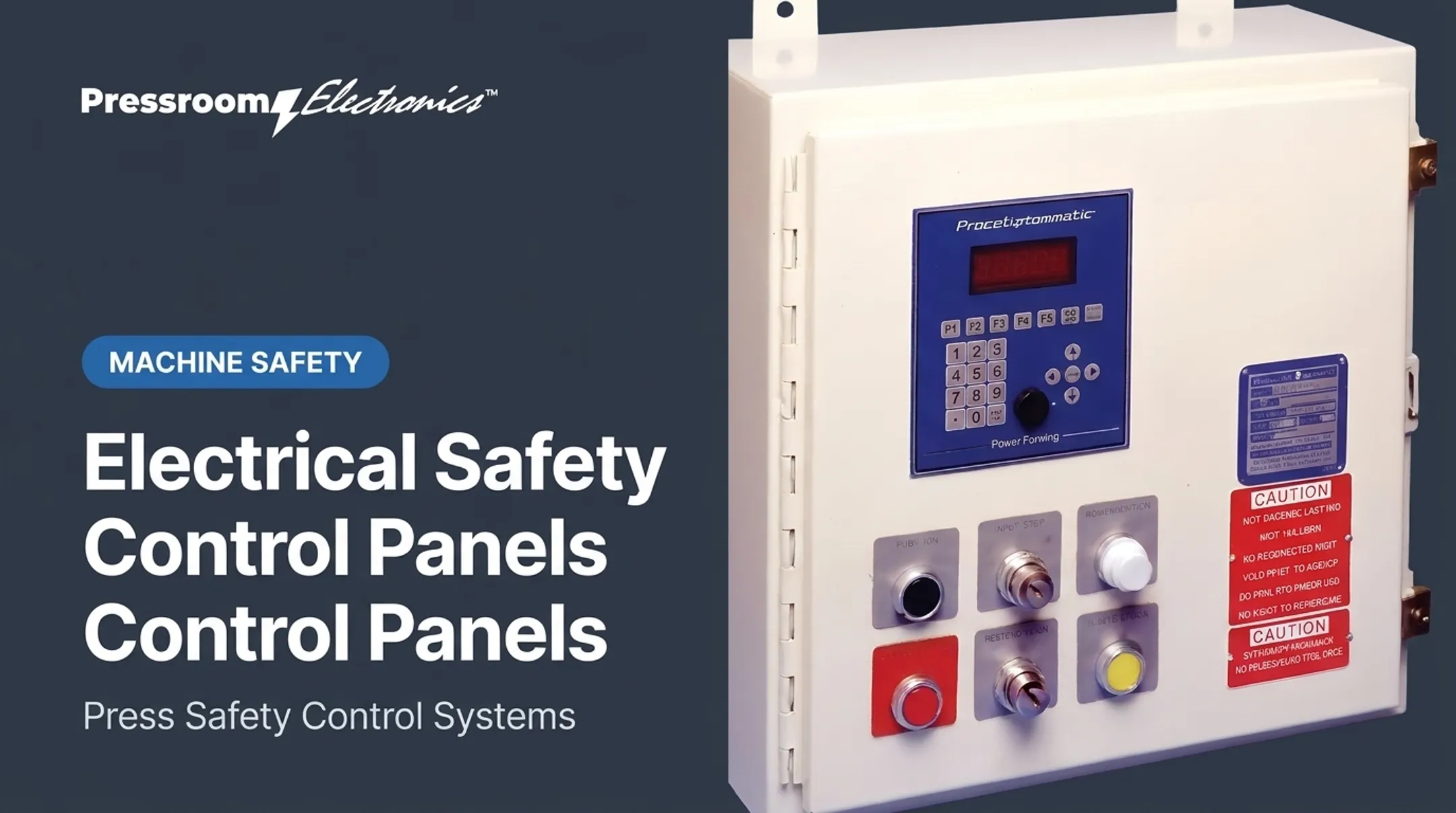
Controls only help when they fit the clutch type, stopping performance, and die work on that machine. Pressroom Electronics designs and builds integrated pressroom controls for stamping and forming equipment in the USA, including:
- Resolver- and rotary-cam-based clutch/brake controls
- Time-based brake monitors
- Die protection
- Light curtains, safety mats, and palm buttons
- Custom programming and service support
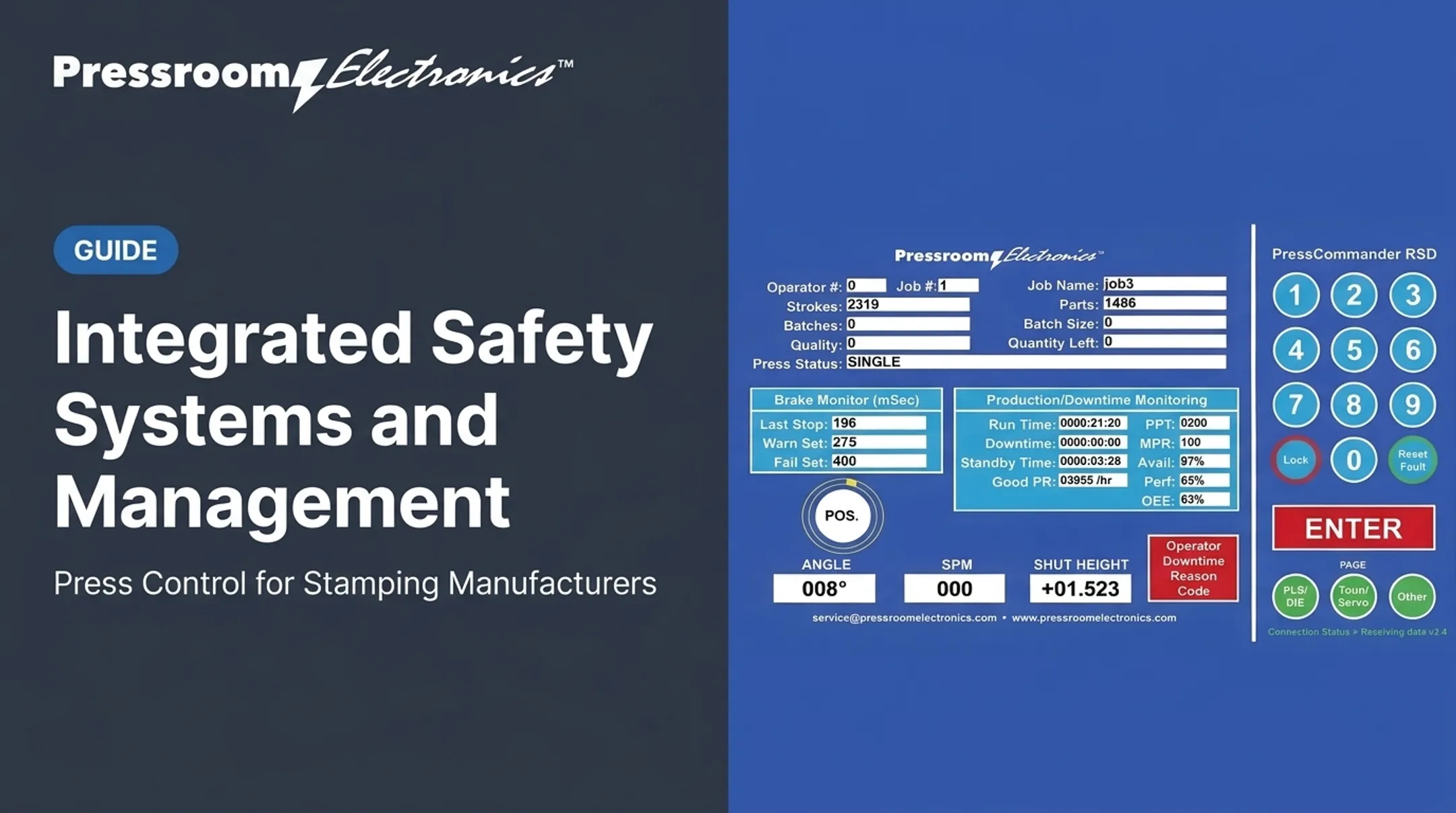
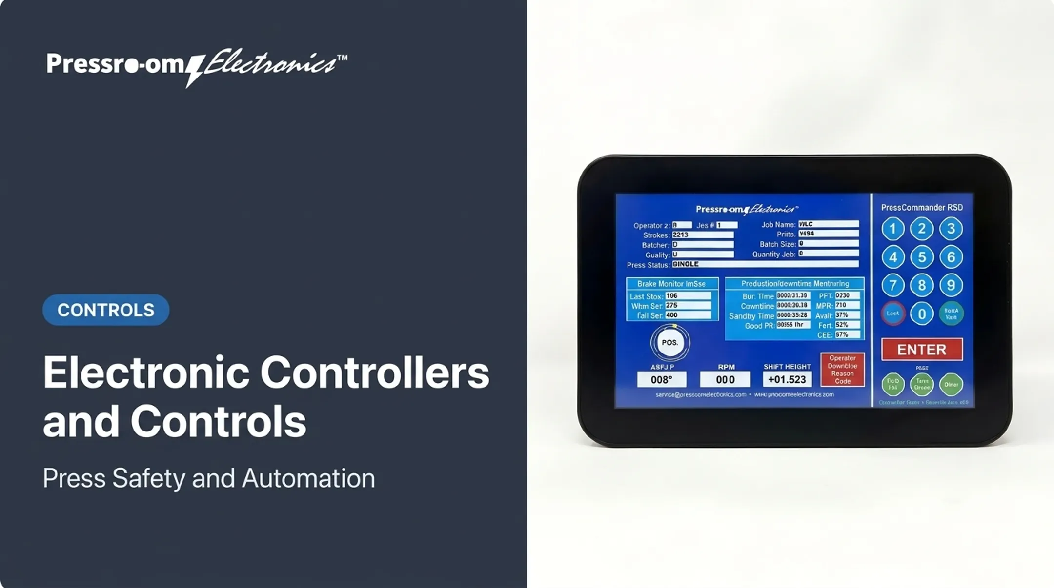
PressCommander, for example, targets part-revolution air-clutch presses and does not apply to full-revolution presses. Review model-specific documentation, programming, compatibility, and support before you buy.
How to Choose a Safety System for a Machine or Press
Match the architecture to the risk and complexity
Start from the risk assessment, then compare relays, controllers, and safety PLCs on:
- Safety I/O count and machine zones
- Required diagnostics and communications
- Future expansion
- Skills available to maintain the system
The cheapest component often isn't the cheapest system. Wiring, commissioning, troubleshooting, training, downtime, documentation, and later changes all add up.
Evaluate retrofit conditions on aging equipment
Legacy presses bring obsolete boards, undocumented wiring, inconsistent schematics, tired cabinets, and limited stopping data. ANSI B11.0-2023 covers modified and rebuilt machinery, and OSHA 1910.217(a)(5) puts responsibility for conformity on whoever modifies or reconstructs a press.
A controls upgrade alone doesn't validate the press. Document a retrofit assessment covering:
- Mechanical condition and clutch/brake performance
- Stopping time and guarding
- Electrical interfaces and replacement part availability
- Production downtime and commissioning access
- Post-upgrade support
Check diagnostics, maintainability, and change control
Good diagnostics point maintenance staff to the affected input, logic condition, output, or fault, so nobody is tempted to bypass. For example, PressCommander displays which safety relay faulted.
Establish change control that includes:
- Password or key access
- Revision-controlled programs and backups
- Current schematics and operator documentation
- Spare-parts planning
- Named authority for safety-related changes
Consider the operating environment and workforce
Contamination, vibration, electrical noise, temperature, washdown, glove use, operator reach, and shift changes all affect device choice and placement. Resolver cables, for instance, should stay away from high-current lines to avoid nuisance faults.
Ask whether operators, electricians, maintenance staff, rebuilders, and OEM personnel can support the chosen architecture for the press's whole service life.
Verify the complete system before production
Test every safety input, logic path, final switching element, restart condition, monitoring function, and fault response before the press returns to production. Include:
- Stop-time measurement at the fastest speed with the heaviest tooling, at 90 degrees
- Safety-distance and clearance validation
- Fault simulation
- Recorded test results
- Revalidation after modifications or program changes
Implementing, Validating, and Maintaining Safety Controls
Installation and commissioning
Follow the approved design, wiring diagrams, manufacturer instructions, and applicable standards. During install:
- Separate safety and standard circuits
- Ground properly and label clearly
- Place components deliberately
- Protect against unauthorized modification
Commissioning should demonstrate the intended response under these conditions:
- Normal operation and restart attempts
- E-stop, guard opening, and presence detection
- Power loss and component faults
Ongoing inspection and preventive maintenance
Build a program that includes:
- Pre-shift checks and periodic functional tests
- Guard, sensor, and wiring inspection
- Brake and clutch evaluation
- Cleaning and sensor alignment
- Testing after maintenance or tooling changes
OSHA 1910.217(e)(1)(i) requires periodic, regular inspections and maintenance records. Weekly clutch/brake, anti-repeat, and single-stroke checks are directed under that rule, though presses that comply with both (b)(13) and (b)(14) are excluded from that weekly cadence. General inspection duties still apply.
Manufacturers such as Pressroom Electronics call for testing the whole system at the start of every shift. Set intervals from manufacturer instructions, standards, risk, conditions, and written site procedures rather than a one-size-fits-all calendar.
Verification, records, and continuous improvement
Keep records of:
- Risk assessments and validation results
- Stop-time measurements and test findings
- Repairs and software revisions
- Bypass events, training, and corrective actions
Treat recurring faults, nuisance trips, unexplained resets, near misses, and production workarounds as root-cause questions. Fix the cause without weakening the protective function.

Frequently Asked Questions
What are the key differences between Cat 3 and Cat 4 safety circuits?
They differ in redundancy, fault detection, fault tolerance, and common-cause expectations under ISO 13849-1. The right category comes from a machine-specific risk assessment and validation, not a component label.
What are the types of safety controls?
Major types include e-stops, guard interlocks, light curtains, safety mats, two-hand controls, safety relays, controllers, safety PLCs, clutch/brake controls, and monitors. Each addresses a different hazard or function.
How does a safety system differ from a standard machine control system?
Standard controls manage production sequence and performance. Safety systems monitor hazardous conditions and execute protective actions, including stopping or blocking restart.
What safety controls are commonly used on mechanical punch presses?
Common ones are point-of-operation guarding, presence sensing, two-hand controls, e-stops, clutch/brake controls, brake monitoring, interlocks, and die protection. The right mix depends on the press and risk assessment.
How do you choose between a safety relay, safety controller, and safety PLC?
Finish the risk assessment first. Then compare safety I/O, zones, diagnostics, communications, expansion, installed cost, maintenance skills, and lifecycle support.
How often should machine safety controls be tested and maintained?
Frequency depends on machine risk, environment, manufacturer instructions, standards, and site procedures. Always test after modifications, faults, repairs, or any change that could affect the safety function.