Introduction
When valves lag, presses miss a stroke, or older HVAC pneumatics drift out of calibration, response gets inconsistent and downtime climbs. A pneumatic control system turns compressed air into controlled mechanical action so machines, valves, dampers, and other equipment move or respond on command.
The term covers more than one setup. It can mean factory-floor machine automation, electro-pneumatic equipment with solenoids and relays, or legacy pneumatic HVAC controls in older buildings.
U.S. pneumatic product shipments reached $5.6 billion in 2024, per NFPA, so these systems are far from obsolete.
This guide covers the definition, the operating sequence, five component groups, industrial and HVAC uses, tradeoffs, selection, safety, and maintenance.
Key Takeaways
- Compressed air creates motion, regulates flow, or carries a control signal.
- Five groups make up the system: supply, preparation and distribution, valves, actuators, and sensors/controllers.
- Performance depends on sizing, clean dry air, leak control, sound logic, and energy isolation.
- Pneumatic devices often sit inside larger PLC or electronic press control architectures.
What Is a Pneumatic Control System?
What the term means
A pneumatic control system uses compressed air to control the direction, pressure, flow, timing, or movement of equipment. The control chain is simple: a sensor or operator input detects a condition, a controller or logic element decides the response, a valve directs air, and an actuator moves.
Air plays two distinct roles:
- Power: air drives a cylinder or rotary actuator.
- Signaling: pressure changes act as an analog command.
Johnson Controls receiver-controllers, for example, accept 3-15 psig signals, while a separate main supply powers the output. Signal range and main supply are not interchangeable. An EP-8000 transducer outputs 3-15 psig but runs on an 18-25 psig main supply.
How it differs from related systems
Pneumatics, hydraulics, and electrics each fit different jobs.
| Approach | Strengths | Tradeoffs |
|---|---|---|
| Pneumatic | Fast short strokes, defined end positions, clean operation | Harder mid-stroke positioning; needs clean, dry air |
| Hydraulic | High force at low cost per unit force | Fluid leakage and maintenance |
| Electric | Precise positioning and motion profiles | Performance depends on application and sizing |
Control architecture varies too:
- A pneumatic-only system uses air logic and mechanical valves
- An electro-pneumatic system adds solenoids and relays
- A PLC-controlled system uses electronic inputs and outputs to command the valves
Compressed air is not automatically the cheapest or most efficient option. Generating it is energy-intensive, so judge the whole system, not just the component price.
How Does a Pneumatic Control System Work?
The five basic components
This five-group breakdown is a practical way to organize the equipment, not a formal standard.
- Air supply. A compressor, receiver tank, and pressure controls provide working air. Capacity must match demand, duty cycle, pressure, leakage, and future expansion.
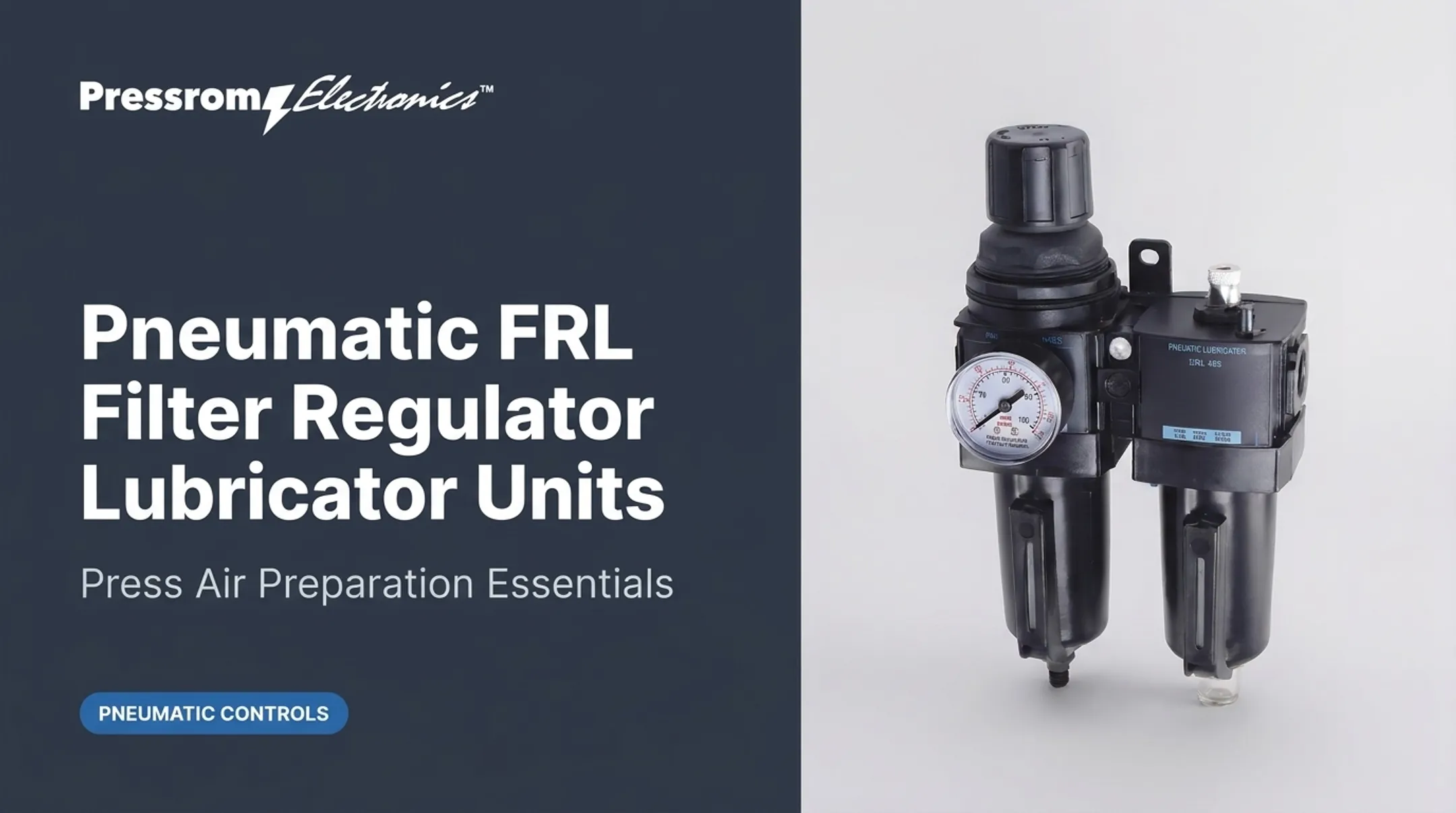
- Air preparation and distribution. Filters, dryers, and regulators clean and stabilize air. Main lines, branches, tubing, and fittings distribute it; long runs, bends, and leaks cause pressure loss.
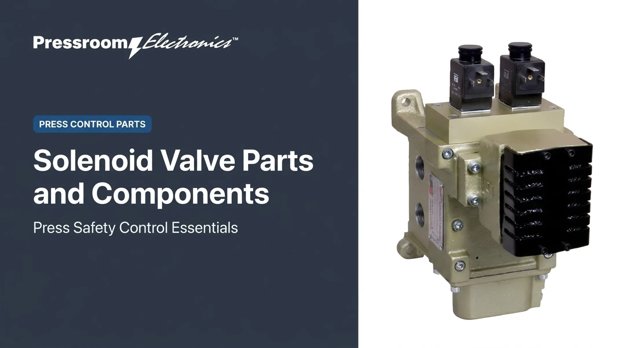
- Control valves. Directional valves open, block, or redirect flow. Pressure valves set available force. Flow controls set how fast an actuator moves.
- Actuators. Cylinders produce linear motion; rack-and-pinion and vane types rotate; diaphragm units position valve closures. Select by force, stroke, speed, load, mounting, and fail position.
- Sensors and controllers. Pressure, flow, proximity, and limit sensors report conditions. Relays, timers, PLCs, and proportional controllers act on them, including magnetic cylinder sensors that read piston position.
A simple input-to-output sequence
Picture a clamping station:
- An operator command or sensor starts the cycle.
- The controller energizes a valve.
- Air enters the cylinder and the actuator clamps the part.
- A position sensor confirms the clamp and signals the next step.
- The valve shifts and the cylinder returns.
Flow controls set travel speed. Regulators set force. Timers and feedback improve repeatability and make stops predictable.

Fail-safe behavior and residual pressure
The right loss-of-air or de-energized position depends on the equipment, the risk assessment, and applicable safety requirements. Spring-return actuators can be arranged fail-open or fail-closed independently.
Stopping also differs from isolating. Some stop functions exhaust air, while others hold pressure to support a load. Trapped air remains stored energy.
Where Are Pneumatic Control Systems Used?
Industrial and manufacturing applications
Common uses include:
- Clamping and gripping
- Positioning and lifting
- Pressing and sorting
- Conveying and packaging
- Material handling
- Guarding and access mechanisms
They suit repetitive automation that needs fast cycling, simple motion, clean operation, and constant loads with clear end positions.
Metal stamping and pressroom applications
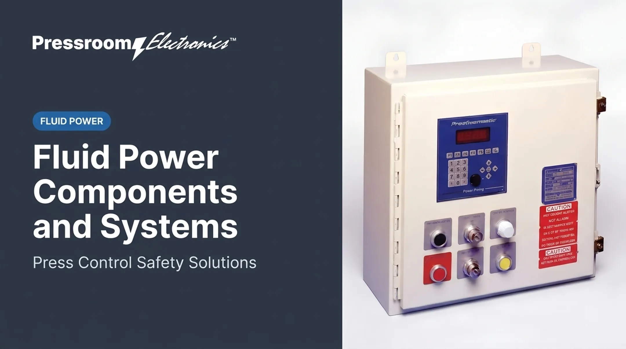
In a pressroom, pneumatic devices handle auxiliary jobs: clamps, part handling, tooling support, valves, and clutch/brake actuation on mechanical presses. The press itself also depends on electronic controls and safety monitoring.
Coordination is the point. Pneumatic functions must work with clutch/brake controls, brake monitoring, die protection, guarding, and production monitoring. Pneumatics does not replace those functions.
Press type matters under OSHA. 29 CFR 1910.217 covers mechanical power presses and excludes hydraulic and pneumatic power presses.
It also requires clutch/brake control to deactivate automatically on loss of engagement pressure, and requires point-of-operation guarding or properly applied protective devices.
HVAC and building control applications
Beyond the pressroom, pneumatic HVAC controls use compressed air to position valves and dampers and regulate airflow and temperature, mostly in older buildings. A damper actuator, for example, moves as diaphragm pressure works against a spring.
Modern DDC and networked automation use electronic signals instead. Hybrid upgrades are common: Johnson Controls' WTL digital pneumatic thermostats retrofit existing pneumatic systems with DDC functionality and remote monitoring, so end devices stay in place.
Benefits and tradeoffs
Benefits:
- Simple mechanical operation
- Rapid actuation
- No electrical power at the actuator
- Smooth modulation in suitable applications
- Usable in some hazardous areas when properly selected and certified
Limitations:
- Compressor energy demand
- Leaks and pressure drop
- Moisture and noise
- Wear and calibration drift
- Limited positioning accuracy in some applications
Air generation has historically accounted for roughly 10% of facility electricity, and 30% or more in some plants, according to a DOE tip sheet from 2004. Pneumatic does not mean explosion-proof or maintenance-free. Components must be rated for the location.

How to Select, Design, and Maintain a Pneumatic Control System
Design and selection checklist
Define these before choosing components:
- Load, force, stroke, and speed
- Cycle rate and response time
- Operating pressure and air quality
- Environment and noise limits
- Control method
- Required fail state
Air quality is classified under ISO 8573-1, which addresses particles, water, and oil.
Safety deserves equal weight. Expect to address machine guarding, lockout, residual pressure, and emergency-stop behavior. OSHA 1910.147 explicitly covers pneumatic energy and stored or residual energy, and control-circuit pushbuttons are not isolation devices.
Relevant guidance includes OSHA 1910.212, ANSI B11.0, B11.1 for mechanical presses, ISO 4414, and ISO 13849-1. Verify current editions and the machine's own risk assessment.
Maintenance and troubleshooting priorities
Prioritize these checks:
- Hunt leaks, ideally with an ultrasonic detector
- Service filters and dryers to manufacturer pressure-drop limits
- Check regulators and verify pressure
- Inspect tubing, fittings, and actuator seals for wear
- Test valve function and sensor alignment
- Log recurring faults
Compressed Air Challenge says leaks can waste 20-30% of compressor output, while a well-maintained system can stay below 10%.

Symptoms point to likely causes:
- Slow or weak movement: leaks, restrictions, low pressure, or undersized parts.
- Erratic motion: contamination, unstable regulation, or faulty feedback.
- Unexpected movement: isolate immediately and bring in qualified people.
Coordinating pneumatic functions with press automation
For metal stamping operations that combine pneumatic devices with electronic press controls, a qualified review can coordinate customized clutch/brake controls, brake monitoring, die protection, guarding, and production monitoring.
Pressroom Electronics designs and manufactures controls for these pressroom applications in the USA. Not every pneumatic installation needs its products, and it does not supply general pneumatic components.
Conclusion
Pneumatic control systems work best when the air supply, components, control logic, safety functions, and maintenance plan fit the application. Evaluate the whole machine or process rather than choosing pneumatics on speed, cost, or safety assumptions alone. Metal stamping shops can discuss integrated press control requirements with Pressroom Electronics.
Frequently Asked Questions
Are pneumatic controls still used?
Yes. They appear in industrial automation, machine auxiliaries, process valves, and legacy HVAC. Many modern installations pair pneumatic devices with electronic or PLC-based controls.
What is a pneumatic control system?
It uses compressed air to control pressure, flow, direction, or movement through valves, actuators, sensors, and logic elements.
How does a pneumatic controller work?
It receives an input, compares or sequences it against the control requirements, and signals a valve or actuator. Feedback closes the loop where needed.
What are the 5 basic components of a pneumatic system?
The five basic components are:
- Air supply
- Air preparation and distribution
- Control valves
- Actuators
- Sensors and controllers
What are some examples of pneumatic control systems?
Common examples include:
- Factory automation, clamping, and material handling
- Robotic tooling and pressroom auxiliary functions
- Process valves
- Pneumatic HVAC dampers and valve actuators
What does pneumatic mean in HVAC?
Pneumatic HVAC controls use compressed air to sense, signal, and position dampers or valves for temperature and airflow control, mostly in older buildings.