Introduction
Moving a load to the same spot, every cycle, sounds simple. It isn't. Commands change, speeds shift, and load conditions drift with every part, tool, and temperature swing.
A servo control system solves this with a closed loop. It takes a command, drives a motor, measures what actually happened, and corrects the difference. The result is regulated position, speed, torque, or a combination.
This article covers the components, the operating sequence, motor and control types, industrial applications (with a focus on stamping), and how to select and integrate a system.
Key Takeaways
- A full servo system combines motor, drive, controller, feedback device, mechanical load, and cabling.
- Feedback lets the system compare commanded motion with actual motion and correct errors.
- Servo motor, drive, and controller are related but do different jobs.
- Sizing, feedback choice, tuning, safety integration, and compatibility decide real-world performance.
What Is a Servo Control System?
A servomechanism is a closed-loop motion system that uses an actuator, a control device, and feedback for continuous correction so the output follows a commanded input.
A servo motor is only one piece. The motor produces motion. The system adds control, power regulation, feedback, and the mechanics of your application.
Three Control Objectives
- Position: a stamping feed that must advance strip exactly 6 inches
- Velocity: a winding or printing axis that holds web speed
- Torque: a tensioning or pressing axis that must hold a set force
Not every application uses all three loops.
Closed Loop vs. Open Loop
An open-loop system sends a command and hopes. It does not compare the result with the reference. A closed-loop system measures the output and responds to error.
Think of driving with cruise control: you set 60 mph, the car senses its speed, and it adjusts the throttle on hills. Command, feedback, correction.
How Does a Servo Control System Work?
A servo control system continuously compares a commanded target with measured feedback and corrects the motor until error approaches zero. The signal path runs command, comparison with measured output, error, drive correction, motor and load, then feedback.
- Command. A PLC, motion controller, CNC, or press control sends a target position, speed, torque, or motion profile.
- Comparison. The drive compares the command with feedback and calculates an error.
- Correction. The drive adjusts current and voltage, the motor changes its output, and feedback confirms the move is approaching the target.

Nested Loops
Servo drives commonly cascade three loops, from inside out: current (torque), velocity, and position. Per Beckhoff documentation, bandwidth drops from inner to outer loops, and the position loop can live in the controller or the drive.
Lag error is the position difference between command and actual.
Mechanics Matter
Acceleration, deceleration, limits, and tuning shape stopping behavior. A large inertia mismatch with a compliant coupling can delay load response and cause overshoot, resonance, and instability. Excessive position gain causes hunting.
Typical trouble sources:
- Poor feedback wiring or grounding
- Incorrect tuning
- Backlash in the transmission
- Overloads
- Mismatched components
These show up as following errors, vibration, overshoot, or nuisance faults.
What Are the Main Components of a Servo Control System?
Servo Motor and Mechanical Load
The motor converts electrical energy into rotary or linear motion. Select it based on the load's torque, speed, inertia, duty cycle, and movement profile. A common brushless construction uses a permanent-magnet rotor and stator windings, with a shaft, bearings, housing, and sometimes a holding brake. A position feedback device is usually mounted on or integrated with the motor.
Servo Drive or Power Amplifier
The drive conditions incoming power and regulates the current and voltage sent to the motor based on commands and feedback. Many drives handle torque and velocity control. Advanced drives add positioning, programming, communications, and safety functions.
Servo Controller
The controller handles the higher-level work: sequencing, trajectory generation, multi-axis coordination, machine I/O, recipes, and PLC or operator communication. Some products combine controller and drive in one device, but the roles stay distinct.
Feedback Device
Feedback reports actual position or velocity.
- Incremental encoder: counts pulses for relative motion; needs a reference after power-up
- Absolute encoder: encodes unique positions, so position is known at startup
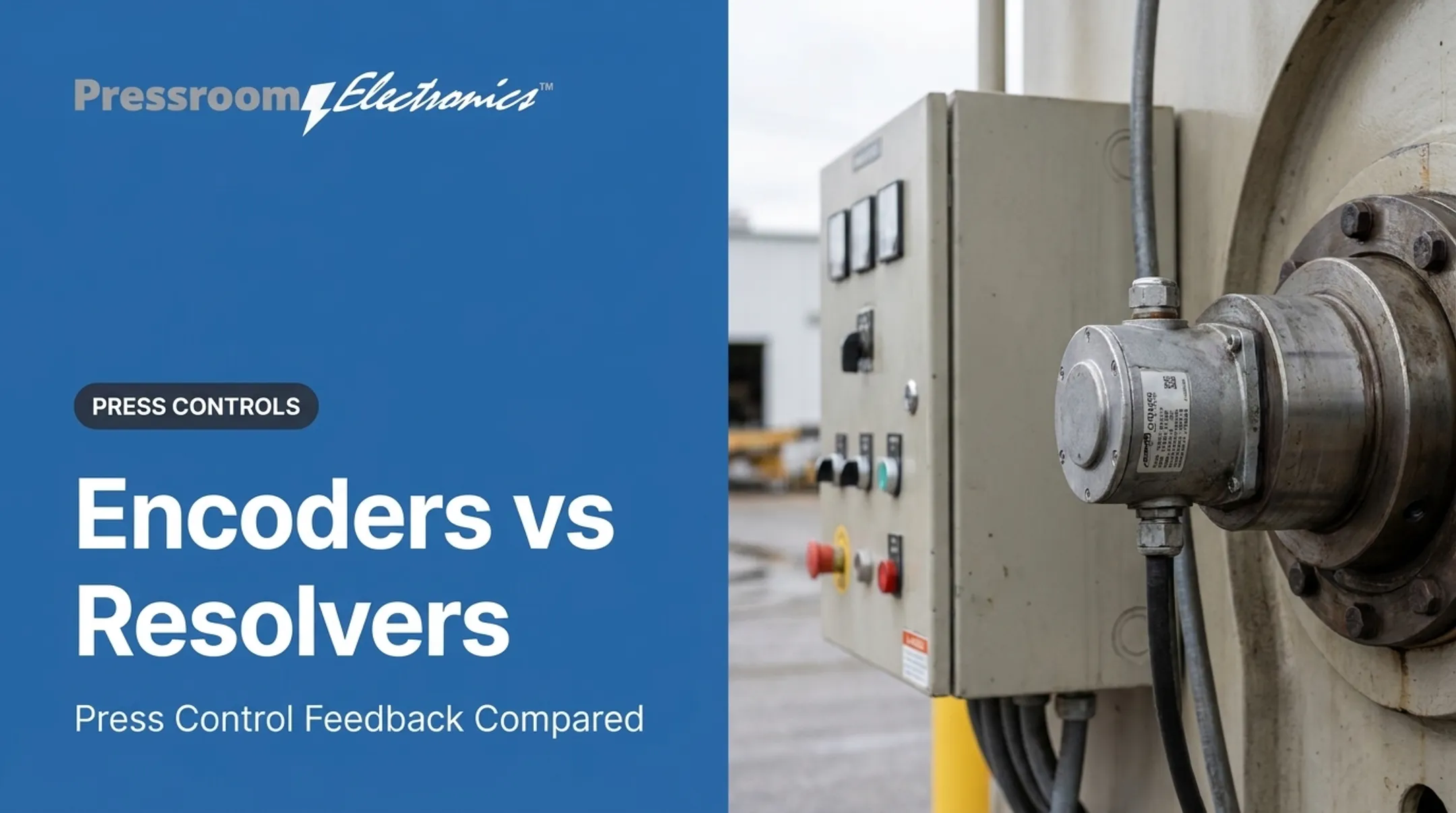
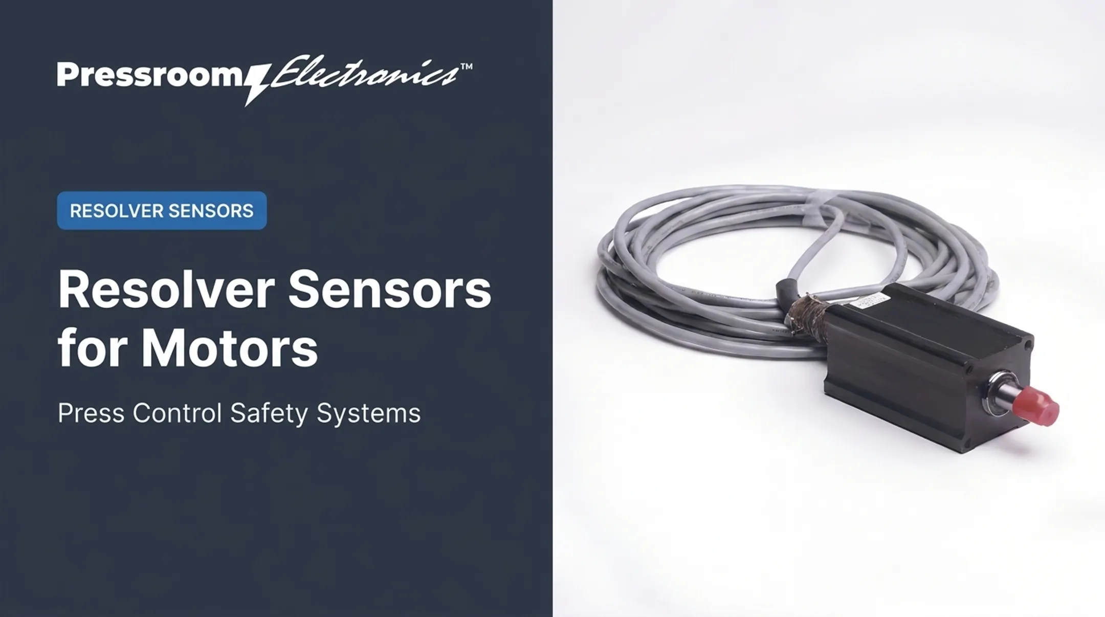
- Resolver: absolute angular feedback, rugged, but needs signal processing
- Linear scale: measures machine position directly, not just motor rotation
- Tachometer: a legacy velocity option
Check resolution and accuracy separately. Motor-side feedback does not directly measure load position or remove backlash.
Resolvers suit pressrooms, where shock, vibration, and contamination are routine. Pressroom Electronics' PressCam 8 Junior uses an industrial brushless resolver for absolute shaft-position feedback, built for shock, vibration, temperature extremes, and oil or coolant mist.
Cabling, Communications, and Safety Interfaces
Motor power cables, feedback cables, network links, shielding, grounding, E-stop circuits, and limits all affect reliability. Rockwell's Kinetix 5700 manual ties improper grounding and shielding to feedback noise and erratic motion.

Networks such as EtherCAT, EtherNet/IP, PROFINET IRT, and Sercos each use their own synchronization method. Verify the OSHA, ANSI, NFPA, and industry requirements that apply to your specific installation. No single compliance claim covers every machine.
What Are the Types, Benefits, and Applications of Servo Control Systems?
Servo System Types and Architectures
- Brushless AC vs. brushed DC: AC permanent-magnet servos use sine-wave commutation. Brushed DC units use brushes that wear and need replacement.
- Rotary vs. linear: Direct linear motors skip the rotary-to-linear transmission.
- Separate vs. integrated: Beckhoff's AMI8100 combines motor, drive, and fieldbus and mounts on the machine without a control cabinet.
Match feedback technology, power rating, environmental protection, and protocol to the application, not to a category label.
Benefits and Tradeoffs
Benefits:
- Precise, repeatable positioning
- Controllable speed and torque
- Fast response to load changes
- Flexible motion profiles
- Potential productivity gains
Tradeoffs:
- More system complexity
- Tuning requirements
- Integration effort
- Feedback sensitivity
- Higher upfront cost
Industrial Applications
- Robotics and CNC: coordinated multi-axis paths
- Packaging and material handling: repeatable indexing and speed matching
- Printing and winding: synchronized velocity and tension
- Inspection: fine positioning for wafer and PCB work
In stamping, P/A Industries documents two servo feeds synchronized by one control, pushing material into the tool while pulling the skeleton away.
For transfers, The Fabricator describes X/Y/Z moves with adjustable distance, velocity, and timing. These work alongside press controls, guarding, brake monitoring, and die protection.
One customer account reported a stamper moving from 45 to 90-100 strokes per minute after adding a servo press. Those results are specific to that application.
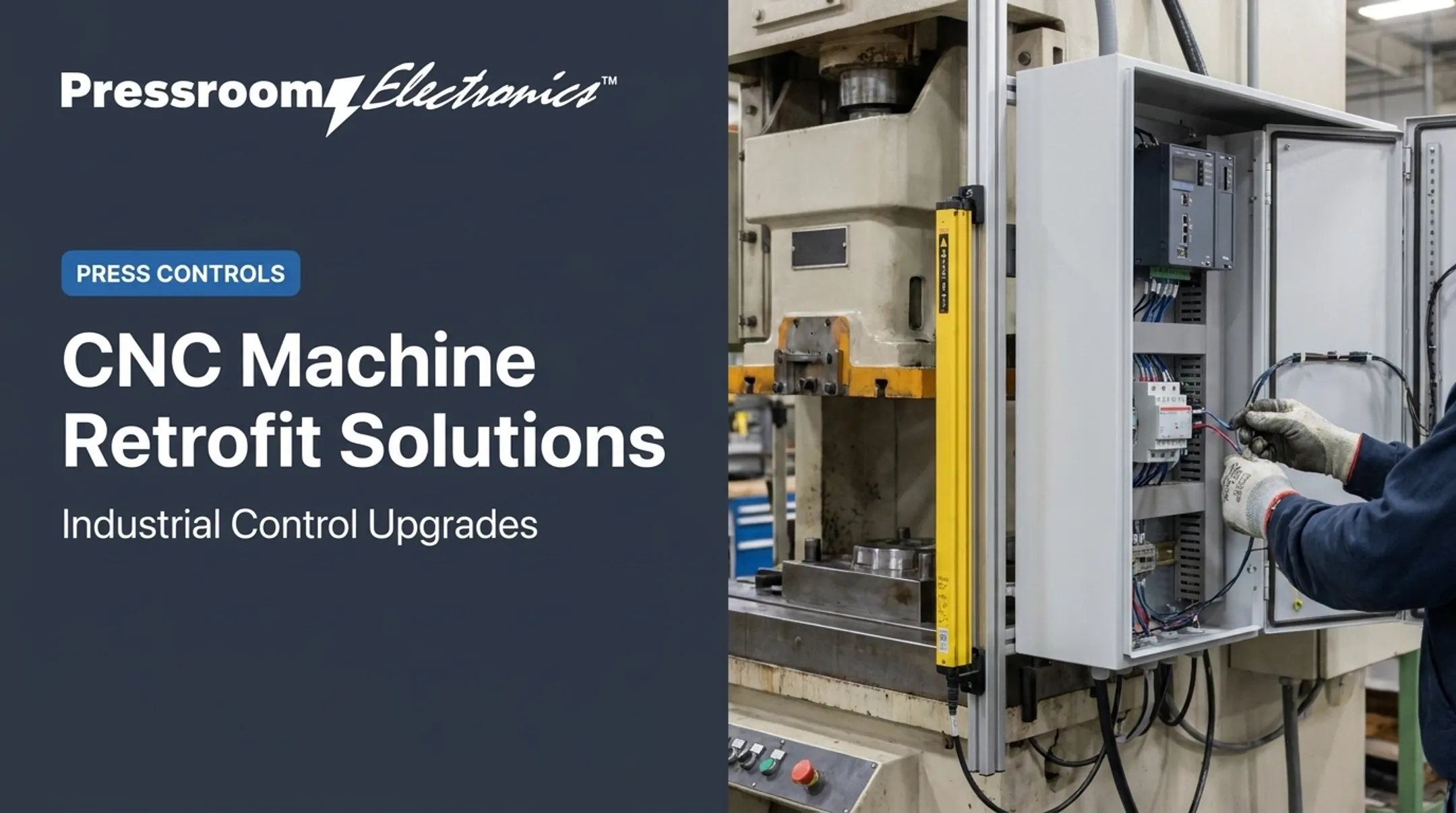
Pressroom Electronics supports pressroom control and automation. Teams evaluating servo-enabled press lines can consider how customized press controls and integrated safety or monitoring functions fit around the motion architecture. For example, the PressCam 8 Junior includes servo feed control with interfaces for several feed makers, plus brake monitoring and die protection.
How to Select and Integrate a Servo Control System
Define Requirements and Size the System
Document before choosing hardware:
- Load mass and reflected inertia
- Torque, speed range, and acceleration
- Duty cycle and travel
- Stopping requirements
- Axis count
- Positioning or synchronization accuracy
Size for both continuous and peak demand. Compare RMS torque with continuous torque, then verify peak torque and duration for the motor-drive pair.
RMS calculations can fail when overload lasts a significant share of the motor's thermal time constant. Use calculations or manufacturer documentation, not rules of thumb. Kollmorgen evaluates mechanics and controls rather than prescribing one universal inertia ratio.
Verify Compatibility, Environment, and Safety
Confirm compatibility before you buy:
- Motor-drive pairing and feedback type
- Voltage, current, and controller capacity
- Protocol, mounting, and cable requirements
Account for temperature, dust, moisture, vibration, and EMI. NEMA Type 4X covers corrosion protection; IEC 60529 IP ratings do not.
Safety belongs in the complete machine design:
- Guarding, E-stops, and limit switches
- Safe stopping and braking
- OSHA 29 CFR 1910.217 for mechanical power presses
- Lockout/tagout under 1910.147
Safe torque off is not electrical isolation, and a holding brake is not energy isolation. Treat stopping, holding, and isolation as separate functions.
Plan Commissioning, Diagnostics, and Maintenance
During commissioning:
- Manage parameters and record them
- Check mechanical alignment
- Verify feedback
- Tune, run test moves, and review alarms
- Document baseline operating conditions
Fault codes speed root-cause analysis. Rockwell's FLT S23 flags AC phase loss, for example, and FLT S20 flags converter overload.
Next steps: gather your application data, read the motor and drive documentation, and bring in a qualified controls specialist when tying servo motion into an existing press or production line.

Frequently Asked Questions
What is a servomechanism?
A feedback-based control system that makes an output follow a commanded position, speed, torque, or other target.
What is the definition of a servo motor?
A servo motor is a motor used in a feedback-controlled motion system. It is built for controlled, responsive movement rather than simple continuous rotation.
What is the difference between a servo drive and a servo motor?
The motor creates mechanical motion. The drive regulates the electrical power and control signals supplied to it.
What is the purpose of a servo controller?
It issues motion commands, sequences operations, generates trajectories, coordinates axes, and handles I/O and communication. Some drives integrate these functions.
How do you control servos?
You send a command, compare it with feedback, and let the drive correct the error, then tune the loops. A PLC, motion controller, CNC, or integrated drive can run it.
Can a servo motor be stopped in any position?
Yes, within system limits. Actual accuracy depends on feedback resolution, tuning, load, backlash, braking, and safety requirements.