Most problems show up at the seams: unclear connector pinouts, confusion between OSSD and conventional NPN/PNP outputs, safety relay inputs that don't match the receiver, and a machine that won't reset after installation.
This guide takes a consistent approach. Identify the signal type first, trace each circuit path, follow the manufacturer's diagram, and validate the whole safeguarding function before the machine returns to service.
Key Takeaways
- Exact wiring depends on the model, output type, connector, safety controller, reset setup, and final switching device.
- A generic diagram teaches; the product manual, risk assessment, and a qualified person decide.
- Dual-channel outputs, reset, EDM, and contactor monitoring belong to one safety function.
- A standard PLC input may report status, but it doesn't provide the stop function.
How Safety Light Curtains Work
What the emitter and receiver do
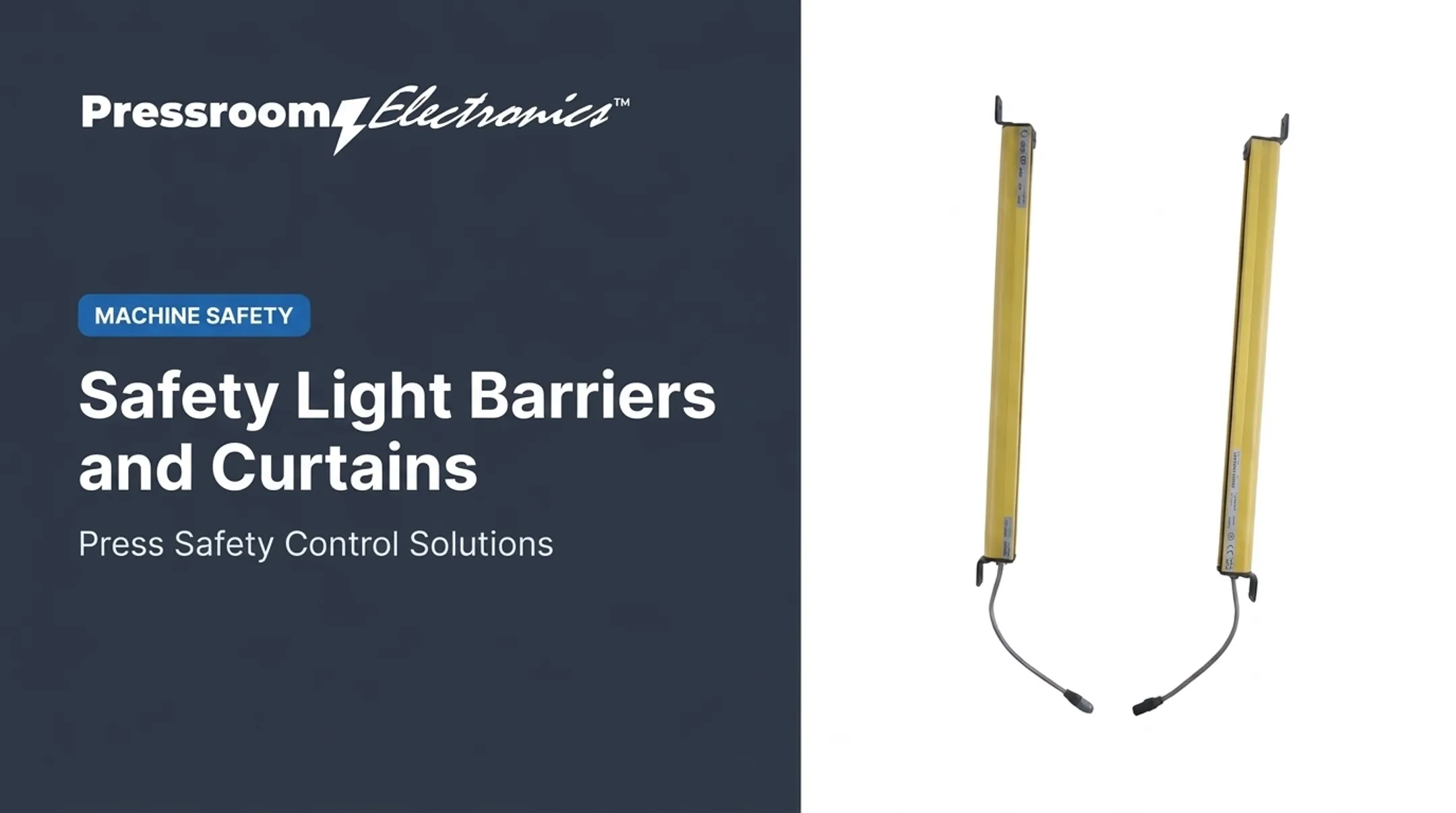
The emitter sends a field of parallel infrared beams. The receiver watches that field. On a press, an automated cell, or an access point, a clear field lets the receiver's safety outputs permit the downstream circuit to run. An interruption switches those outputs to the safe state.
SICK's deTec4 manual describes exactly this: interrupting one or more beams changes the output signal switching devices (OSSDs).
A simple functional chain looks like this:
- DC power feeds the emitter and receiver.
- The receiver's OSSD1 and OSSD2 feed a safety relay or safety PLC.
- The safety device drives redundant contactors or a safety-rated drive input.
- Those devices remove power from the machine actuator guarding the hazard zone.
Safety signals on a diagram
OSSD1 and OSSD2 are two separate safety outputs that report the receiver's safe or unsafe state to compatible safety equipment. Confirm exact behavior in the product manual.
OSSDs differ from conventional NPN, PNP, and dry relay outputs. Similar symbols or wire colors don't make them interchangeable. PNP and NPN describe transistor topology, and some OSSDs are built on either: Omron's F3SG-SR series offers wiring-selectable PNP or NPN OSSDs.
Why signal type matters
A mismatch between output and input can mean no signal, inverted logic, nuisance trips, or an unsafe design. Never infer signal type from wire color alone.
Voltage range, current limits, test pulses, and input compatibility are model-specific. As one benchmark, Banner's EZ-SCREEN LS specifies two sourcing OSSDs at 0.5 A maximum each, with test pulses around 200 µs wide. Other models differ, so read your own manual.
How to Read a Safety Light Curtain Wiring Diagram
Start with the device documentation
Before tracing a wire, pull these details from the manual:
- Model number and connector style
- Pinout and output type
- Supply requirements and synchronization method
- Reset options, plus EDM or test terminals
Manufacturers differ even for similar functions. On Banner's eight-pin receiver connector, pin 7 is earth/chassis. On the SICK deTec4 system connector, pin 7 is 0 V. Treat each pinout as its own document.
Trace power and reference conductors
Identify each of the following and check it against the manual:
- Positive DC supply
- 0 V/common
- Protective or functional earth
- Any overcurrent protection
Polarity, supply stability, and grounding matter. Banner warns that poor earth grounding can cause random trips and lockouts, and says to route emitter and receiver cables away from power, motor, servo, and other noisy wiring.
Follow the emitter and receiver paths
The emitter typically carries power and synchronization. The receiver adds safety outputs, test, reset, and monitoring connections. Synchronization varies by brand. SICK devices synchronize optically, while Banner LS units need matching scan codes.
Follow the safety output path
Both receiver outputs run to compatible dual-channel inputs on a safety relay or safety PLC. That device then controls contactors, safety outputs, or another approved final switching arrangement. Rockwell's GuardShield manual requires both OSSDs be processed separately, and either one switching off must produce a safe state.

A standard PLC input can monitor status or diagnostics where permitted. It is not a substitute for the safety-rated path.
Check reset and feedback circuits
Automatic reset re-enables outputs once the field clears. Manual reset (restart interlock) holds them off until someone acts. Typical diagrams show a reset pushbutton and EDM contacts from positively guided contactors.
Reset is not start. SICK requires a separate machine Start after the restart interlock is reset.
E-stops, gate switches, and other safeguards often need their own inputs or separately evaluated channels. Don't casually wire them in series with an OSSD circuit. Banner notes series interlocks can mask failures and don't reach Category 4.
Common Safety Light Curtain Wiring Configurations
Dual-channel OSSD to a safety relay or safety PLC
This is the primary arrangement for modern guarding:
- Power the emitter and receiver per the manual.
- Route OSSD1 and OSSD2 independently to compatible safety inputs.
- Connect reset and EDM as the safety controller specifies.
- Let the final outputs drive redundant contactors, a safety-rated drive input, or another approved means of removing hazardous motion.
Keep the two OSSD channels separate. The light curtain manual must define the receiving terminals and test-pulse compatibility.
Conventional NPN or PNP outputs
A PNP output sources current toward positive. An NPN output sinks toward common. The receiving input must match the selected type.
A generic three- or four-wire sensor diagram usually lacks the fault detection, dual-channel monitoring, reset, and redundancy a safety function requires.
Dry relay-contact outputs
A relay-output curtain is a set of contacts. It supplies no voltage of its own, so an external control circuit must power through it. You can combine normally closed contacts with a safety relay, reset logic, and contactor monitoring. Follow the manufacturer's contact ratings and approved architecture.
Curtains with controllers or integrated relays
Some systems put monitoring, test, reset, or switching in a dedicated controller. Before connecting the machine circuit, confirm whether the controller handles power distribution, test input, EDM, relay outputs, or manual reset.
Choosing the architecture for a press
Let the hazard drive the choice. Factor in:
- Stopping time and access pattern
- Required performance level
- Existing clutch/brake or drive controls
- Whether an operator can stand inside the guarded area
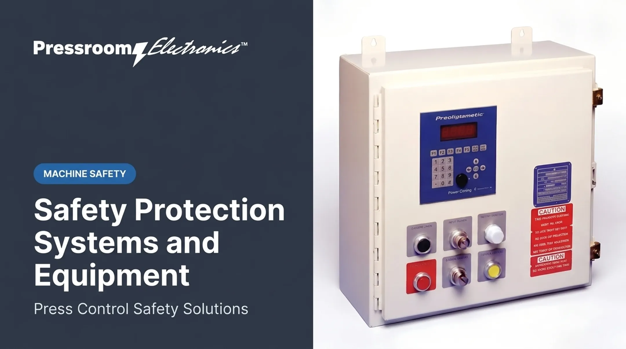
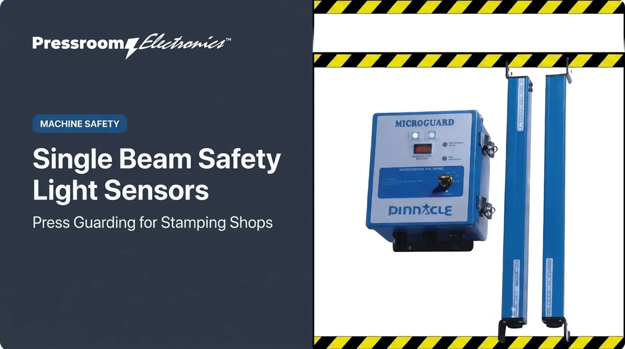
Pressroom Electronics, for example, offers light curtains with PNP solid-state outputs and others with captive-contact dry safety relays, plus press controls with a dedicated light guard input. Shops retrofitting mechanical punch presses can review its guarding and press-control solutions as part of the overall design. None of that replaces a risk assessment.

Installation and Validation Checklist
Before energizing
- Verify the model-specific schematic and supply polarity.
- Check conductor identification, terminal tightness, and connector seating.
- Confirm grounding, cable routing, and protective devices.
- Confirm the safety relay or safety PLC is compatible.
Use lockout/tagout and qualified personnel. OSHA 1910.147 requires an energy-control program and verified isolation before covered servicing.
Functional checks after wiring
- Check emitter/receiver alignment and clear-field status.
- Interrupt the beams and confirm both output channels respond.
- Test manual reset and restart prevention.
- Test E-stop response.
- Confirm contactor or drive feedback.
The machine should not restart automatically when a person could remain in a hazardous area. Verify your reset strategy against the risk assessment and equipment manual.
Documentation and validation
Record the as-built diagram, device settings, test results, fault indications, and changes from the original design. Banner calls for commissioning checks, shift or daily checks, and six-month checks, with results kept near the machine or in its technical file.

For presses, confirm current requirements in OSHA 1910.217, ANSI B11.1, B11.19, and the manufacturer's manuals. OSHA's rule excludes hydraulic and pneumatic presses, and safety distance calculations use stopping time measured at about 90 degrees of crank rotation. Don't make compliance claims without that groundwork.
Troubleshooting Common Wiring Problems
The receiver does not power on
Verify each item against the documentation:
- Supply voltage and polarity
- 0 V connection
- Fuse condition
- Connector seating
- Supply capacity
- Synchronization requirement (if used)
Don't apply a different supply type just because a connector fits.
Outputs stay off or the PLC reads the wrong state
Confirm the receiver output type (OSSD, NPN, PNP, or relay contacts) matches what the input supports, and that both channels are wired as documented.
Likely causes:
- Beam misalignment or dirty optics
- Incorrect test or EDM wiring
- Incompatible test pulses
- Short or cross circuits
- A latched fault
SICK notes that contamination triggers a weak-signal indication, and lists OSSD short circuits, cross circuits, or overload as wiring-fault possibilities.
The system won't reset or keeps tripping
Work through the checks in order:
- Reset mode and reset pushbutton (SICK notes a defective or held button blocks reset)
- Clear-field condition
- Contactor feedback (SICK flags EDM faults when feedback doesn't change within 300 ms)
- E-stop state
- Safety relay diagnostics and receiver indicators
Use the manufacturer's procedure and qualified personnel. Never bypass safeguards, jumper safety inputs, or short live conductors as a quick test.
Frequently Asked Questions
What is the basic wiring diagram?
DC power feeds the emitter and receiver. The receiver's safety outputs go to a compatible safety relay or safety PLC, which drives the machine's final stopping elements. Exact terminals vary by model.
How does a light curtain work?
An emitter creates a field of infrared beams and a receiver detects interruptions. When the field is broken, the receiver sends a stop signal through the machine's safety control system.
Can a safety light curtain connect directly to a PLC?
A standard PLC can monitor status only. A safety PLC or safety controller can carry the safety function. The device manual and required performance level determine the architecture.
What is the difference between OSSD, NPN, and PNP outputs?
OSSD is a safety-oriented dual-channel output arrangement. NPN and PNP describe transistor switching logic. Don't substitute one wiring method for another without confirming compatibility.
Why is my safety light curtain not resetting?
Common causes include a blocked or misaligned beam, wrong reset configuration, an open E-stop, an EDM or contactor feedback fault, incompatible wiring, or a latched fault on the receiver or safety relay.